16
6.4 Wiring
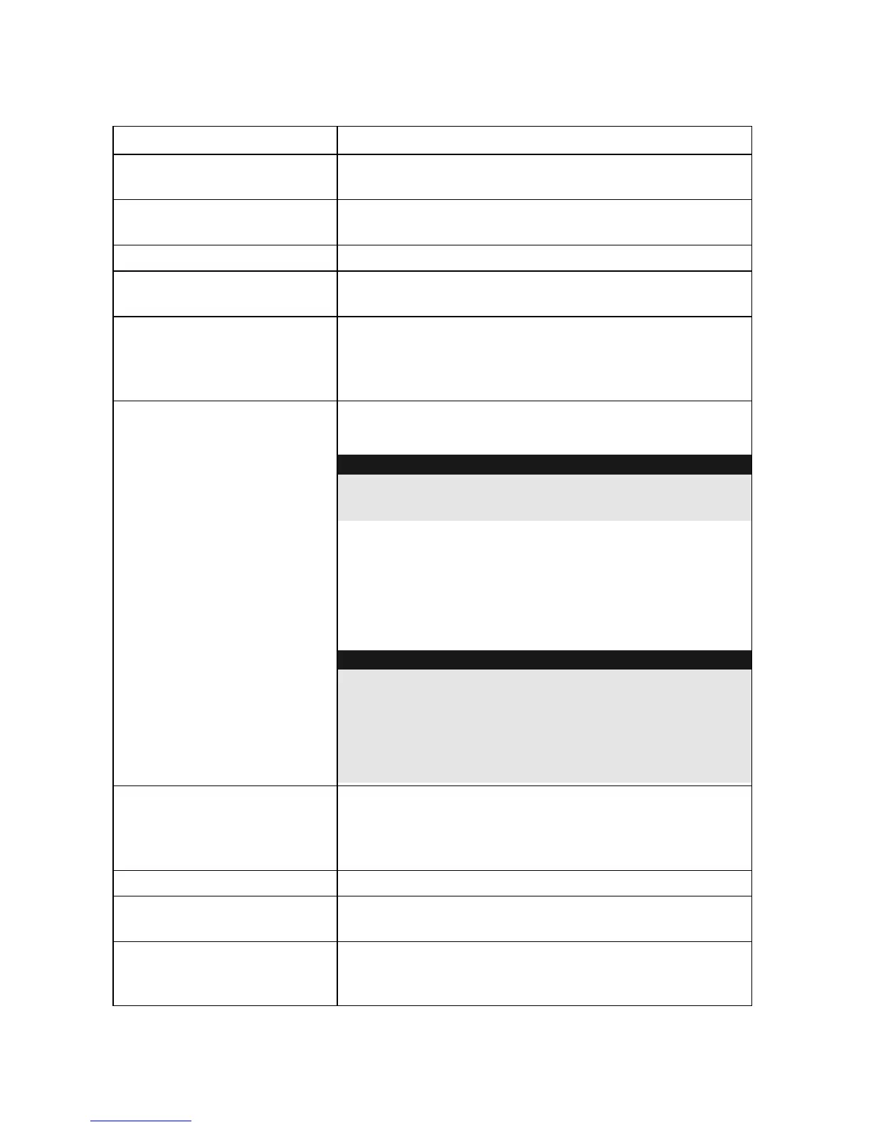
Terminal Description
LED
Connector for LED2. The LED lights up for a negative
trigger signal (0 V DC at input).
AUX RED
COM BLK
Standard connections for power supply (13.8 V
DC/200 mA max.).
BUS YEL / BUS GRN
Not used.
SPEAKER
Connections for the sounder speaker (8 Ohm,
30 W).
BLK
RED
Connections for the backup power supply (12 V/2.1
Ah).
The battery is charged automatically by the auto-
recharging battery circuit.
PS +
PS -
Optional connections for power supply (13.8 V DC/
1.6 A).
IMPORTANT:
If you use a battery, there is no need to connect these
terminals!
These connections are required if you do not want to
use a battery.
The maximum current from these connections is 1.6
A. The AUX RED and COM BLK connections can be
left free.
IMPORTANT:
Make sure that the power source supplies the
necessary current of 1.6 A; otherwise, the alarm
system cannot work correctly!
Note that the compact alarm has no backup power
supply if connected like this!
TAMPER R
TAMPER F
JP3 (PCB)
Tamper connections for wall and cover contact. The
connection of the contacts depends on the TAMPER
jumper.
The tamper contacts are connected to the JP3 pins.
PROX (N.C)
Not used.
TRBL (N.O)
The reaction of the trouble output depends on the
setting of the dip-switch (CONFIG 1).
C+
- Connected to +12 V »»» sounder is off
- Loss of +12 V signal (or switch to
0 V
 Loading...