13
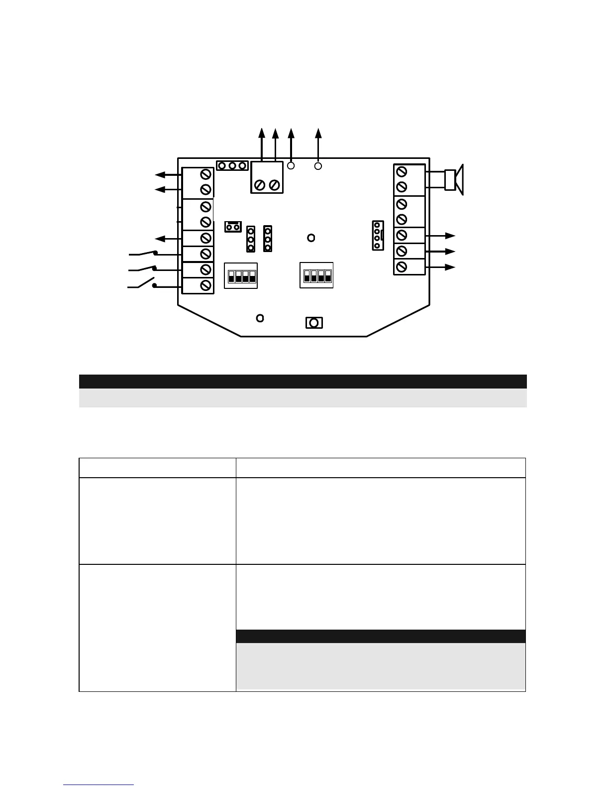
6. Putting into operation
BUS
GRN
YEL
COM
BLK
SPEAKER
AUX
RED
LED
TRBL
PROX
TAMPER
F
R
C + C - ST
1234
ON
ID1
TAMPER
PS
+
-
BLK
RED
MAN
AUTO
C +
C -
TRIG STROB
LED2
POWER
To Internal
Speaker
13.8VDC ,
200 mA (max)
INT EXT
Optional
13.8VDC
1.6 A
To
Battery
Tamper Output
(0.5A, 24V N.C)
Anti Approach
Output
(0.1A, 24V N.C)
Status LED2
On/Off
Trouble Output
70 mA max
1234
ON
CONFIG
+ 12 V
COM(-)
COM(-)
(To Int.
Tamper)
IMPORTANT:
Before connecting, make sure that the power supply is switched off!
6.1 LED indication
LED Description
POWER
The power LED shows the operating state of the
sounder.
ON: Power supply is applied to the sounder.
OFF: No power supply to the sounder.
FLASHING: Sounder trouble.
LED2
Status LED
ON: Input signal at LED input.
OFF: No signal at input.
IMPORTANT:
The signal to the LED is user-defined, e.g.: alarm
system set. But you can also combine the input of the
Status LED with the output of the fault output (TRBL).
Power
supply
(optional)
Battery
Power supply
Status LED
NC tamper
output
Trouble output
Sounder input -
Strobe input -
Sounder input +
Sounder
speaker
JP3