Do you have a question about the AC Infinity AC-TWT8 and is the answer not in the manual?
Details essential safety guidelines to prevent fire, electric shock, and injury during installation and operation.
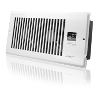
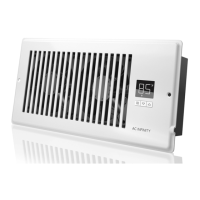
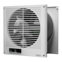
Durable, fire-resistant ABS faceplate with internal steel structure shielding fan blades and motor.
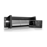
Features an innovative EC motor for pulsing speed control, offering longer lifespan and quieter operation.
Enables mounting in any direction with a motor boasting a 67,000 hours lifespan.
Automated programs include adjustable levels, temperature triggers, timers, cycles, and custom transitions.
Cutting-edge rotor design allows electronic reversal of rotation for intake or exhaust airflow.
Telescopic cylinder design allows unit to expand and contract to fit walls 3.5" to 6" thick.
The main unit of the through-wall fan.
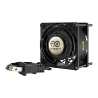
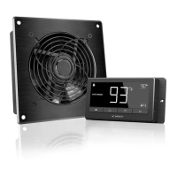
An accessory for the rear installation of the fan.
Eight screws provided for securing the fan to the wall.
Stencil used for marking the front installation points.
Stencil used for marking the rear installation points.
Component for mounting or securing wires.
Select an unobstructed location and mark center point, mounting points, and cylinder outline.
Measure wall length (X) and height (Y) from the center point for reference.
Drill mounting holes and cut the circular outline for the fan opening using a saw.
Insert the included anchors into the pre-drilled mounting holes.
Align and insert the rear faceplate into the circular cutout, ensuring mounting holes line up.
Drill wood screws into the anchors to firmly secure the rear faceplate.
Use measurements from Step 2 to mark the front faceplate stencil on the other side of the wall.
Place the stencil over the center point and mark mounting points and cylinder outline for the front.
Drill mounting holes and cut the circular outline for the front opening, using a saw if recommended.
Insert the included anchors into the mounting holes for the front faceplate.
Insert the front faceplate into the cutout, ensuring alignment with the rear faceplate's cylinder.
Route the power cord through the opening or prepare for hardwiring for a cordless appearance.
Drill wood screws into the anchors to secure the front faceplate to the wall.
Plug the AC power cord into a wall outlet to connect power and operate the fan.
Ensure power is shut off. Unplug fan and turn off the room's circuit breaker.
Use a non-contact voltage tester to confirm wires are fully depleted of electricity before proceeding.
Unscrew the leftmost panel to access the power cord wires within the fan unit.
Unscrew the three bolts to release the power cord wires, noting wire color references.
Remove the power cord and its wires from the fan's junction box.
Route house wires into the junction box, connect correct colors to rails, and secure the panel.
Explains the function of Mode, Setting, and Up/Down buttons for controlling the fan.
Details the meaning of Probe Temperature, Controller Mode, Current Level, Countdown, and User Setting.
Instructions on how to switch airflow between INTAKE and EXHAUST using button combinations.
How to set the fan for intake airflow using the setting and up buttons for 3 seconds.
How to set the fan for exhaust airflow using the setting and down buttons for 3 seconds.
Overview of available programming modes: OFF, ON, AUTO, TIMER TO ON, TIMER TO OFF, and CYCLE.
Sets the minimum fan speed for other modes and the speed used when triggered to turn off.
Sets the fan speed for active operation, establishing the maximum speed in other modes.
Sets high temp trigger; fan activates if probe meets/exceeds threshold, ramping speed up or down.
Sets low temp trigger; fan activates if probe meets/falls below threshold, ramping speed up or down.
Sets a countdown to trigger fan operation at the speed set in ON Mode.
Sets a countdown until fan operation stops at the speed set in ON Mode.
Sets continuous on and off durations for the fan to cycle, running at ON/OFF mode speeds.
Explains settings for DISPLAY, °F/°C, CALIBRATION TEMPERATURE, and TRANSITION TEMPERATURE.
Adjusts display brightness and enables auto-dimming feature on levels A2 and A3.
How to lock the controller, turn the display off, and turn it back on.
Changes displayed units between Fahrenheit (°F) and Celsius (°C).
Adjusts the temperature reading from the sensor probe in 2°F (or 1°C) increments.
Adjusts the threshold between fan speeds in AUTO Mode temperature triggers.
Explains alert icons for Timer, Display Lock, Intake Airflow, and Exhaust Airflow status.
Resets the controller to factory settings, clearing all user parameters.
Locks the controller to prevent adjustments or mode switching. Holding setting button unlocks.
Locks settings and allows turning the display off while programs continue running.
Allows jumping to OFF Mode by holding the mode button, disabled if controller is locked.
Resets current mode value to OFF or 0. Up/down buttons restore last setting.
Increases or decreases user setting automatically by holding up or down button.
Use a portable sensor like a stud finder to locate studs, drains, and obstructions before installation.
Tools recommended for installation include pencil, ruler, tape measure, screwdriver, drill, and drywall saw.
Hardwiring is not required; the fan can be powered via its three-pronged plug into an electrical socket.
Not recommended for bathrooms, windows, fire-rated walls, or outside walls due to moisture/durability.
Disconnect power, remove faceplates to clean blades and grilles with mild detergent and water.
CLOUDPLATE series rack fan system for cooling audio, video, home theater, network, and IT equipment racks.
CLOUDLINE series duct fans for ventilating AV rooms, closets, and DIY air circulation/exhaust projects.
AXIAL series fan kits for DIY projects requiring cooling or ventilation, includes guards and mounting hardware.
Product free from manufacturing defects for two years from purchase date; covers defects, malfunctions, or unusability.
Does not cover abuse, misuse, physical damage, water submersion, incorrect installation, or normal wear.
Contact customer service team at support@acinfinity.com to initiate a product warranty claim.
| Manufacturer | AC Infinity |
|---|---|
| Model | AC-TWT8 |
| Type | Inline Duct Fan |
| Size | 8 inches |
| Noise Level | 35 dBA |
| Material | Plastic |
| Weight | 6.5 lbs |
| Display | Yes |
| Speed Settings | 10 |
| Controller | Included |
| Ducting Compatibility | 8-inch |