SC24-36 Controller
Page 2
Soil Moisture Sensors
– Knob position for setting sensor thresholds and for manually
reading the sensors.
Soak Cycle
– Knob position for setting soak cycle run and soak durations for each zone.
Flow Management
– Knob position for setting zone and tap water flow rates for
automatic management of simultaneous zone watering.
Test
– Tests valve solenoid currents, wire leakage, sensor currents and valve operation.
Allows sequential activation of zones for checking sprinkler heads.
Event Pause
– Knob position for programming future events during which you do not
want watering to occur.
Advanced Options
– Knob position for adjusting display contrast, setting up multiple
zone watering, reading messages, etc.
Water Budget/Rain
Delay
– Knob position for setting seasonal adjustments and rain
shutoffs for clock driven zones that do not utilize sensors. Sensor zones accommodate
weather conditions automatically.
Zones –
These positions access each individual zone and are used for assigning the
zones to programs, for setting zone run times and for manually watering zones.
6. Pull tabs to access inside wiring terminals.
Controller Installation
Mounting the Controller
1. For safe, reliable operation select an installation site which will provide:
Protection from direct irrigation spray
Protection from direct sunlight during the hottest part of the day
Access to a 110 volt circuit that is not controlled by a light switch nor feeds a noisy load
such as a large motor.
Access to a #6 to #10 grounding wire and copper clad ground rod.
Access to the sprinkler control valve wiring.
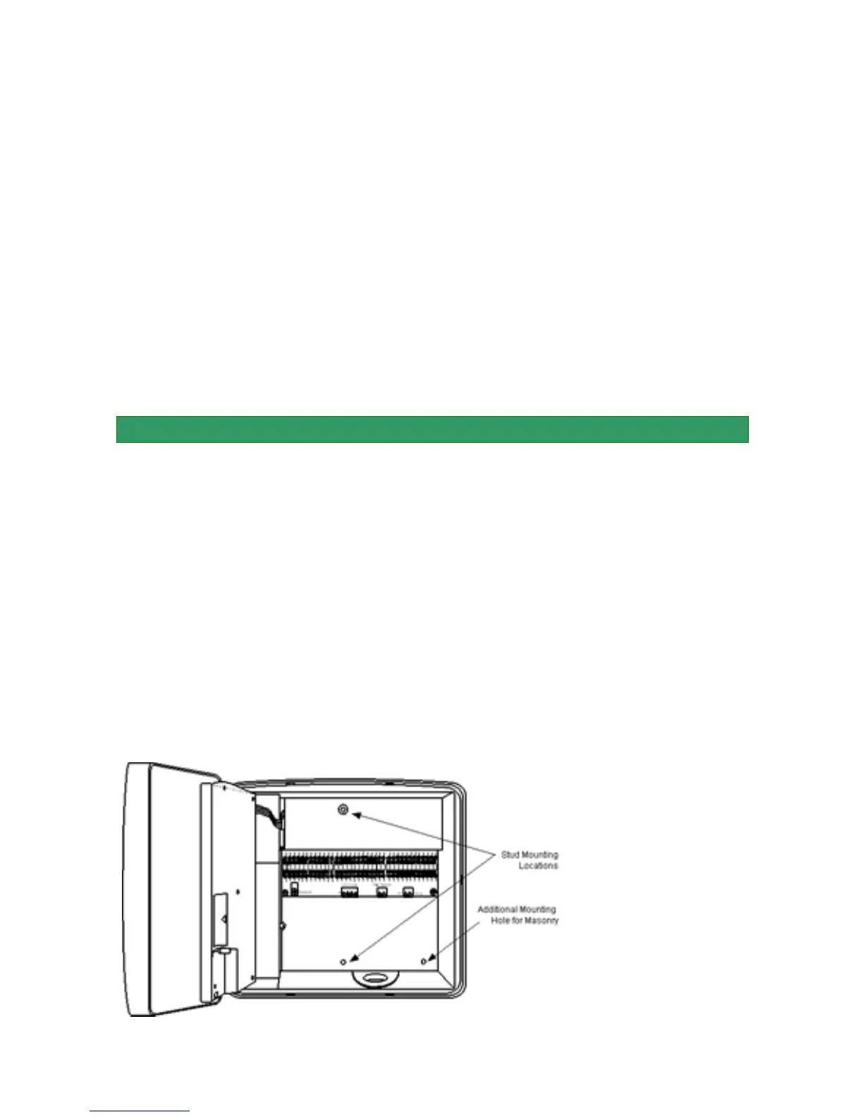
2. Securely mount the controller through the stud mounting locations or the optional
masonry mounting hole using appropriate wood screws or concrete anchors (not
included).
NOTE
: If installation will be on drywall or masonry, install screw anchors to assure secure
mount.
3. Use a 1/2" metal
conduit coupling to attach
a connection box to the
power nipple on the
bottom of the controller as
shown in the diagram
below.
4. Drill a hole in the
bottom of the controller
box to install a 1/2"
conduit for the ground
wire as shown below.