Installation and Operation Manual
Page 3
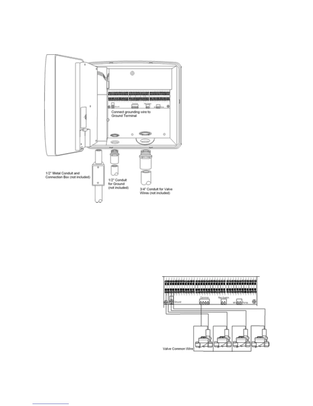
NOTE
: Conduit, adapters, grounding rod, and wires are not provided. Install conduit and
adapters as required by local electrical codes.
5. Clip out the knock-out from the
large hole in the bottom of the
controller and install a 3/4" conduit
for the zone wires. If a larger hole
is needed use a hole saw to
enlarge the provided hole. The
knock-out can be used to guide
the drill bit for the hole saw.
Connecting the Valves
Each zone has a valve that controls the flow of water to the zone. Control wires from
these valves must be connected to the controller.
1. Route the valve wires from the valves into the controller as depicted in the schematic
below.
2. Attach the common wire to one of the 4 common terminals. Tighten down the screw.
3. Strip the insulation from the zone wires back 1/2". Push the zone wires into the push-in
terminal strips. If you need to remove the wire press the black lever on the terminal strip
with a screwdriver then pull out the wire.
4. If you are using a pump with your sprinkler
system connect the pump relay wire to the
terminal labeled 'Pump'. If you are using a
Master Valve with your system connect the
wire from the master valve to the terminal
labeled 'MV'. Note that the pump can be
configured to turn on with selected zones.
The Master Valve turns on with all zones.
NOTE
: If you are installing an Acclima Flow and Pressure Meter the Master Valve will be
connected to the black wires on the Flow and Pressure Meter module rather than to the
controller.