38
Connector Information
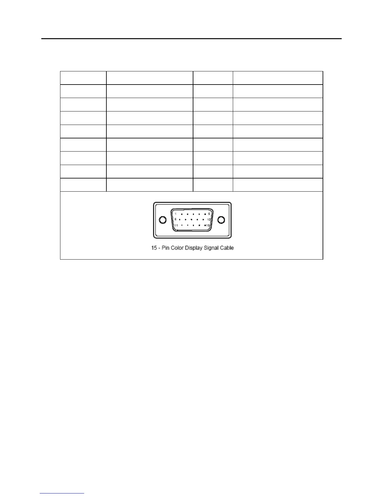
The following figure shows the connector locations on the main board:
Pin No. Description Pin No. Description
1. Red Video 9. +5V
2. Green Video 10. Logic Ground
3. Blue Video 11. Monitor Ground
4. Monitor Ground 12. DDC-Serial Data
5. DDC-Return 13. H-Sync
6. R-Ground 14. V-Sync
7. G-Ground 15. DDC-Serial Clock
8. B-Ground
Chapter 5
 Loading...