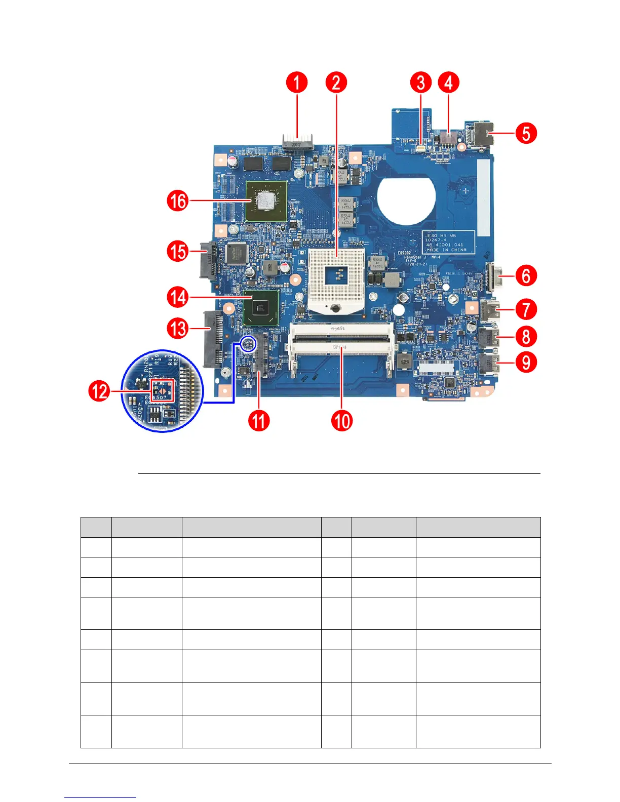
5-4 Jumper and Connector Locations
Figure 5-2. Bottom View (Discreet)
Table 5-2. Mainboard Bottom
No. Code Component No. Code Component
1 BAT1 Battery connector 9 USB2 USB port
2 CPU1 Processor socket 10 DM1-2 Memory slots 1 and 2
3 FAN1 Fan connector 11 WLAN1 WLAN module slot
4 DCIN1 DC power cable connector 12 G2201 Clear password
hardware gap
5 RJ45 Ethernet jack 13 HDD1 HDD connector
6 CRT1 Monitor port 14 PCH1 Mobile Intel HM65
Express Chipset
7 HDMI1 HDMI out port 15 ODD1 SATA optical drive
connector
8 USB1 USB port 16 VGA1 NVIDIA GeForce
graphics controller
 Loading...