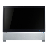
Hardware Specifications and Configurations 1-13
CPU/System
VRD
Monitor System Ambient Temp
Monitor CPU Temp
H61 PCH bridge temperature
Fan Speed:
Monitor CPU fan speed
Voltage
Vcore /+12V / +5V / +3.3V / 5VSB
Design Criteria:
Designed in CPU Over temperature warning/shut down circuit
Linear mode control for CPU/System/North bridge FAN separately by individual
sensor
PWM function should cover ACPI mode and non-ACPI mode
Support thermal shutdown mechanism
System LED Definition 0
Power State LED
S0 Blue Steady
S3 Amber Steady
S4/S5 Off
Storage State LED
N/A
Current and Voltage on LED 0
The Blue/Amber LED (for Power switch LED) current and voltage bias must follow
“LED Definition v1.4 in Appendix”
Voltage bias: 5V
Current: 20mA
All On-board Connectors List 0
Rear I/O connectors
1 HDMI-in port
1 HDMI-out port
4 USB 2.0 ports
1 RJ45 LAN port
1 DC power jack
Side I/O connectors
1 MS/SD/MMC card reader connector
1 B-Cas card reader connector (BOM option; for Japan SKU only)
2 audio jacks (MIC/Headphone)

 Loading...


