31 Chapter 3
No Procedure Photo
When reassembling the DMD
Module, please be aware of
the following Notes.
Note1:
The DMD Heasink Spring
Plate should be placed as the
picture shows.
Note 2:
The DMD Insulator Mylar &
DMD Heatsink Backer Plate
should be placed as the
picture shows.
Note 3:
The DMD Chip should be
reassembled as the picture
shows.
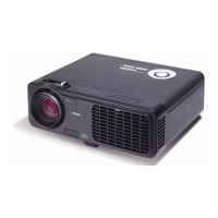
5 Unscrew 1 screw to remove
the Color Wheel.
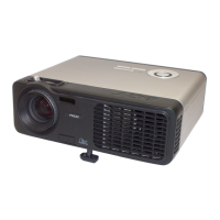
6 1. Unscrew 2 screws to
remove the Zoom Ring &
Stopper.
2. Unscrew 3 screws to
remove the Focus Ring.
Zoom Ring
Zoom Ring Stopper
 Loading...