Do you have a question about the Acksys AirLink V2 and is the answer not in the manual?
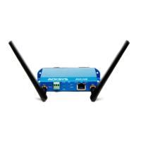
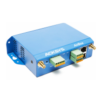
Connect antennas to Ant.1 and Ant.2 connectors. Use Ant.1 for single, Ant.1/Ant.2 for dual.
Device has two power sources: DC connector or PoE. Turns on automatically when power is applied.
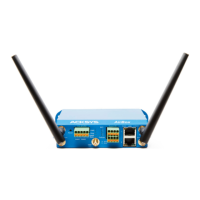
Plug Ethernet cable into LAN connector. Check LAN LED. Use LAN connector for PoE.
Use WaveManager to change the IP address or enable DHCP client for network compatibility.
Access the device's web interface by selecting the product in WaveManager and clicking "Details" then "Web Interface".
Enable Wi-Fi radio, select country for regulation rules, and click Save & Apply.
Configure default wireless settings like mode, SSID, security, and channel. Save settings to prevent loss.
Place the device in an appropriate location.
Position antennas for proper communication, ensuring line of sight with peer devices.
Evaluate the device's Access Point role using a second PC with wireless connection.
Evaluate the device's Client role using two ACKSYS devices and a second PC with LAN connection.
Check power supply and cabling if no LEDs are lit.
Verify remote device power, Ethernet connections, try a different cable or device.
Ensure Wi-Fi interface is enabled, parameters match, check radio conditions, and try disabling security.
Check WaveManager network scan range, ensure firewall is not blocking it.
Restore settings via browser or by pressing the reset button for 2 seconds during boot.
Reset button accessible from back panel. Use non-metallic object.
Connect to ground using the power terminal block or grounding tab with a braided metal wire.
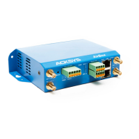
Details the 3-way terminal block for EARTH, VIN+, VIN- signals for power supply.
Describes the RJ-45 female connector supporting Auto-negotiation for 10/100/1000 Mbps speeds.
Describes using Ant.1 for single antenna or Ant.1/Ant.2 for dual. Recommends 50 ohms terminator for unused connectors.
Use two Ø4 holes on the case for fixing.
Product can be mounted on a DIN RAIL using the WL-FIX-RD2 kit.
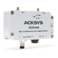
Indicates the product is powered on by the connector or PoE source.
Shows initialization status, ready state, or hardware/firmware issues.
Indicates LAN link status and activity, including connection speed.
Shows if the radio is enabled, disabled, or associated.
Indicates radio Tx/Rx activity.
Details dimensions, weight, enclosure rating (IP 30), and operating/storage temperature ranges.
Covers device configuration, firmware upgrade, SNMP, operating modes, network topology, and security features.
Details DC power (9-48VDC) and PoE requirements, number of ports, and Ethernet port type.
Details number of interfaces, radio modes (802.11a/b/g/n), modulation rates, frequency ranges, and number of antennas.
Details output power for different modes (802.11b/g, 802.11a, 802.11gn HT20/HT40, 802.11an HT20/HT40) with 1 or 2 antennas.
Provides reception sensitivity values for different Wi-Fi modes and conditions (MCS).
Device conforms to council directive and is CE marked.
Lists FCC ID (Z9W-RMB) and IC ID (11468A-RMB) for Wi-Fi interface.
| Wireless Standards | IEEE 802.11 a/b/g/n |
|---|---|
| Maximum Data Rate | 300 Mbps |
| Frequency Bands | 2.4 GHz, 5 GHz |
| Mounting | Wall mounting |
| Security | WEP, WPA, WPA2 |