5.4 Multi-purpose inputs and outputs
Acqiris SA240P User's Manual 61
5.4 Multi-purpose inputs and outputs
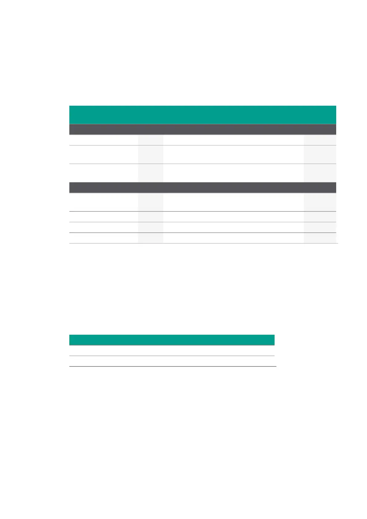
The multi-purpose I/O connectors may be used for any of the functions shown in the following table:
IO Connector
Functions
Type Description of signal
Mode /
Option
Notes
Inputs
Disabled - IO connector is disabled.
In-AccumulationEnable Level
This signal controls the execution of the
averaging sequence.
-AVG IO 1 only
In-TriggerEnable Level
Digitizer
mode
IO 2 only.
Outputs
Out-AcquisitionActive Level
Indicates that the acquisition is currently run-
ning.
IO2 only
Out-AnalyzerArmed Level Indicates that the acquisition is ongoing. -AVG IO 3 only
Out-LowLevel Level Fixed 'low' level signal for debug purposes.
Out-HighLevel Level Fixed 'high' level signal for debug purposes.
Table 5.3 - List of signals selectable for the programmables I/Os .
The list of Available signals is indicated (as a comma separated list) by member
IAqMD3ControlIO.AvailableSignals (IVI.NET) or attribute AQMD3_ATTR_CONTROL_IO_
AVAILABLE_SIGNALS (IVI-C).
Signal Logic Levels
The multi-purpose IO signals are 3.3 V CMOS compatible (5V Tolerant buffer). The levels shown in
the table below should be observed.
Direction Low level High level
Input < 0.8 V > 2.0 to 3.45 V
Output In the range 0 to 0.8 V In the range 1.6 to 3.3 V
Table 5.4 - Logic levels.
As an Input
The input is high-impedance and will be pulled high if unconnected via an internal weak pull-up (10 k
pull-up resistor).