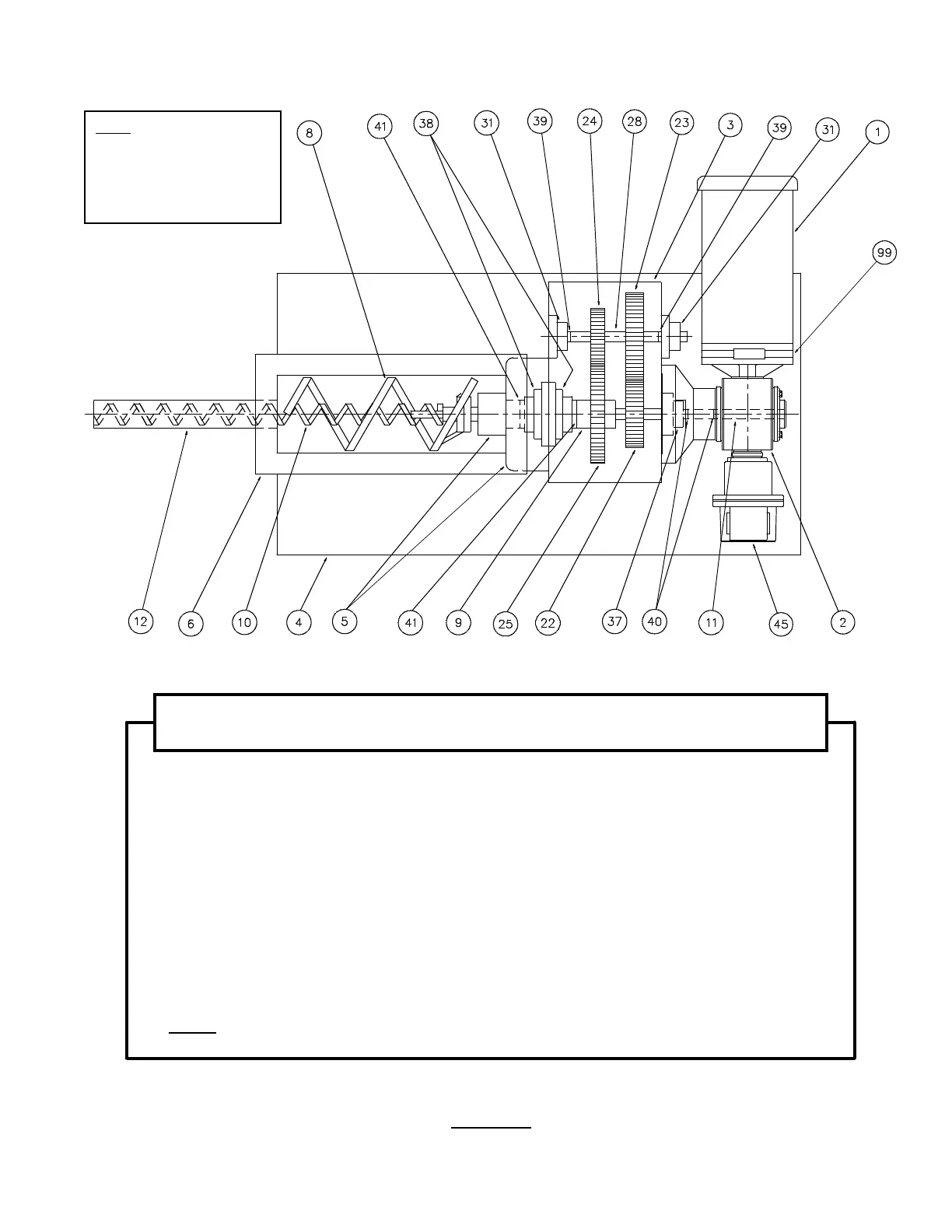
FIGURE 2
NOTE:
The Numerical Component
designations indicated in this
Illustration are for reference
purposes only for use within
this Instruction Manual.
'28%/(&21&(175,&$8*(5'5,9(
7\SH3%*HDUER[
1.
Motor
2.
Gear-reducer
3.
Gearbox
4.
Feeder Mounting Base
5.
Seal Housing Assembly
6.
Conditioning Chamber
8.
Conditioning Auger (Intromitter)
9.
Conditioning Auger Drive Shaft
10.
Metering Auger
11.
Metering Auger Drive Shaft
12.
Discharge Cylinder
22.
“A” Drive Gear with key
23.
“A” Driven Gear with key
24.
“B” Drive Gear with key
25.
“B” Driven Gear with key
28.
Countershaft
31.
Bearings (Countershaft)
37.
Bearing (Metering Auger
Drive Shaft)
38.
Bearings (Conditioning Auger
Drive Shaft)
39.
Snap Rings (Countershaft)
40.
Snap Rings (Metering Auger
Drive Shaft)
41.
Snap Rings (Conditioning Auger
Drive Shaft)
45.
Tachometer (Optical)—Optional
99.
Tachometer (Magnetic)—Optional
NOTE:
Only one Tachometer (45 or 99) is furnished (when a variable speed DC
drive is used).
25