AR-B1579 User's Guide
2-11
(5) Printer Control Latch & Printer Control Swapper
The system microprocessor can read the contents of the printer control latch by reading the address of printer
control swapper. Bit definitions are as follows:
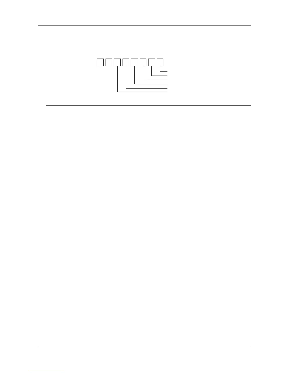
XX
12345670
STROBE
AUTO FD XT
INIT
SLDC IN
IRQ ENABLE
DIR(write only)
Figure 2-3 Bit’s Definition
NOTE: X presents not used.
Bit 5: Direction control bit. When logic 1, the output buffers in the parallel port are disabled allowing data driven
from external sources to be read; when logic 0, they work as a printer port. This bit is write only.
Bit 4: A1 in this position allows an interrupt to occur when ACK changes from low state to high state.
Bit 3: A1 in this bit position selects the printer.
Bit 2: A0 starts the printer (50 microseconds pulse, minimum).
Bit 1: A1 causes the printer to line-feed after a line is printed.
Bit 0: A0.5 microsecond minimum highly active pulse clocks data into the printer. Valid data must be present for
a minimum of 0.5 microseconds before and after the strobe pulse.