AR-B1579 User’s Guide
3-6
Name Description
SBHE [Input/Output]
The System Bus High Enable indicates the high byte
SD8 - SD15 on the data bus
-MASTER [Input]
The MASTER is the signal from the I/O processor which
gains control as the master and should be held low for a
maximum of 15 microseconds or system memory may
be lost due to the lack of refresh
-MEMCS16
[Input, Open collector]
The Memory Chip Select 16 indicates that the present
data transfer is a 1-wait state, 16-bit data memory
operation
-IOCS16
[Input, Open collector]
The I/O Chip Select 16 indicates that the present data
transfer is a 1-wait state, 16-bit data I/O operation
OSC [Output]
The Oscillator is a 14.31818 MHz signal used for the
color graphic card
-ZWS
[Input, Open collector]
The Zero Wait State indicates to the microprocessor
that the present bus cycle can be completed without
inserting additional wait cycle
Table 3-2 I/O Channel Signal Description
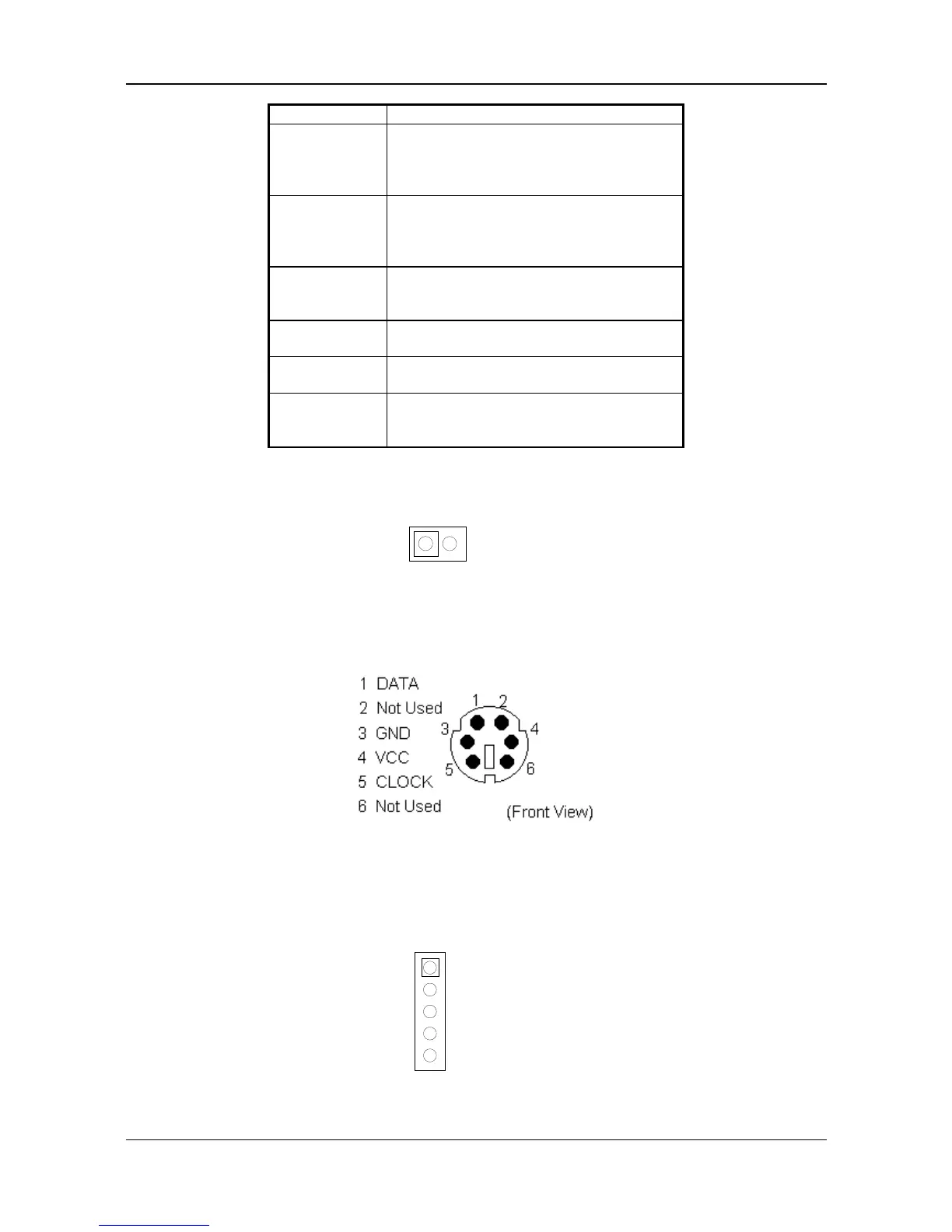
3.2.5 Keyboard Connector
(1) Keyboard Lock Header (J7)
1
2
KBLK
GND
12
Figure 3-7 J7: Keyboard Lock Header
(2) 6-Pin Mini DIN Keyboard Connector (CN9)
Figure 3-8 CN9: 6-Pin Mini DIN Keyboard Connector
(3) AUX. Keyboard Connector (J12)
A PC/AT compatible keyboard can be used by connected the provided adapter cable between J12 and the
keyboard. The pin assignments of J12 connector are as follows:
2 DATA
4 GND
1 CLOCK
5 VCC
3 Not Used
J12
Figure 3-9 J12: AUX. Keyboard Connector