AR-B1579 User’s Guide
3-2
3.2 SYSTEM SETTING
Jumper pins allow you to set specific system parameters. Set them by changing the pin location of jumper blocks.
(A jumper block is a small plastic-encased conductor [shorting plug] that slips over the pins.) To change a jumper
setting, remove the jumper from its current location with your fingers or small needle-nosed pliers. Place the
jumper over the two pins designated for the desired setting. Press the jumper evenly onto the pins. Be careful not
to bend the pins.
We will show the locations of the AR-B1579 jumper pins, and the factory-default setting.
CAUTION: Do not touch any electronic component unless you are safely grounded. Wear a grounded wrist strap
or touch an exposed metal part of the system unit chassis. The static discharges from your fingers can
permanently damage electronic components.
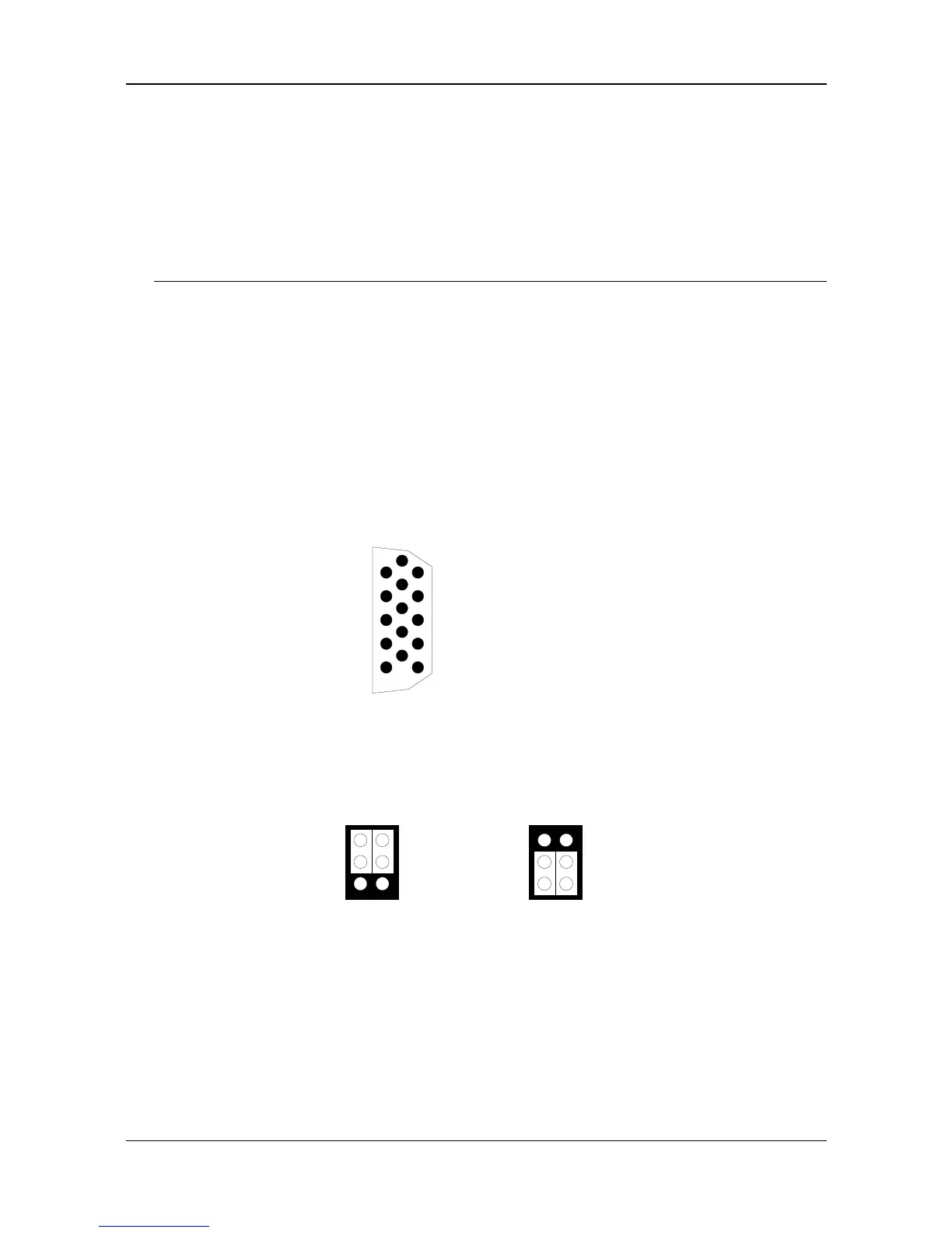
3.2.1 CRT CONNECTOR (DB1)
The AR-B1579 supports CRT color monitors. It can be connected to create a compact video solution for the
industrial environment. It allows a maximum CRT resolution of 1024X768. For different VGA display modes, your
monitor must possess certain characteristics to display the mode you want.
To connect to a CRT monitor, an adapter cable has to be connected to the DB1 connector. DB1 is used to
connect with a VGA monitor when you are using the on-board VGA controller as a display adapter. Pin assignments
for the DB1 connector are as follows:
DB1 (CRT Connector)
6
10
15
111
2
3
4
5
1 Red
2 Green
3 Blue
13 Horizontial Sync
14 Vertical Sync
4, 9, & 11 Not used
5 & 10 Ground
6, 7 & 8 AGND
12 DDC DATA
15 DDC CLOCK
Figure 3-2 DB1: CRT Connector
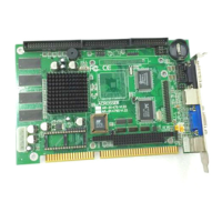
3.2.2 Watchdog Transferring Select (JP6)
1
3
2
5
4
6
Standard Mode