AR-B1579 User's Guide
3-9
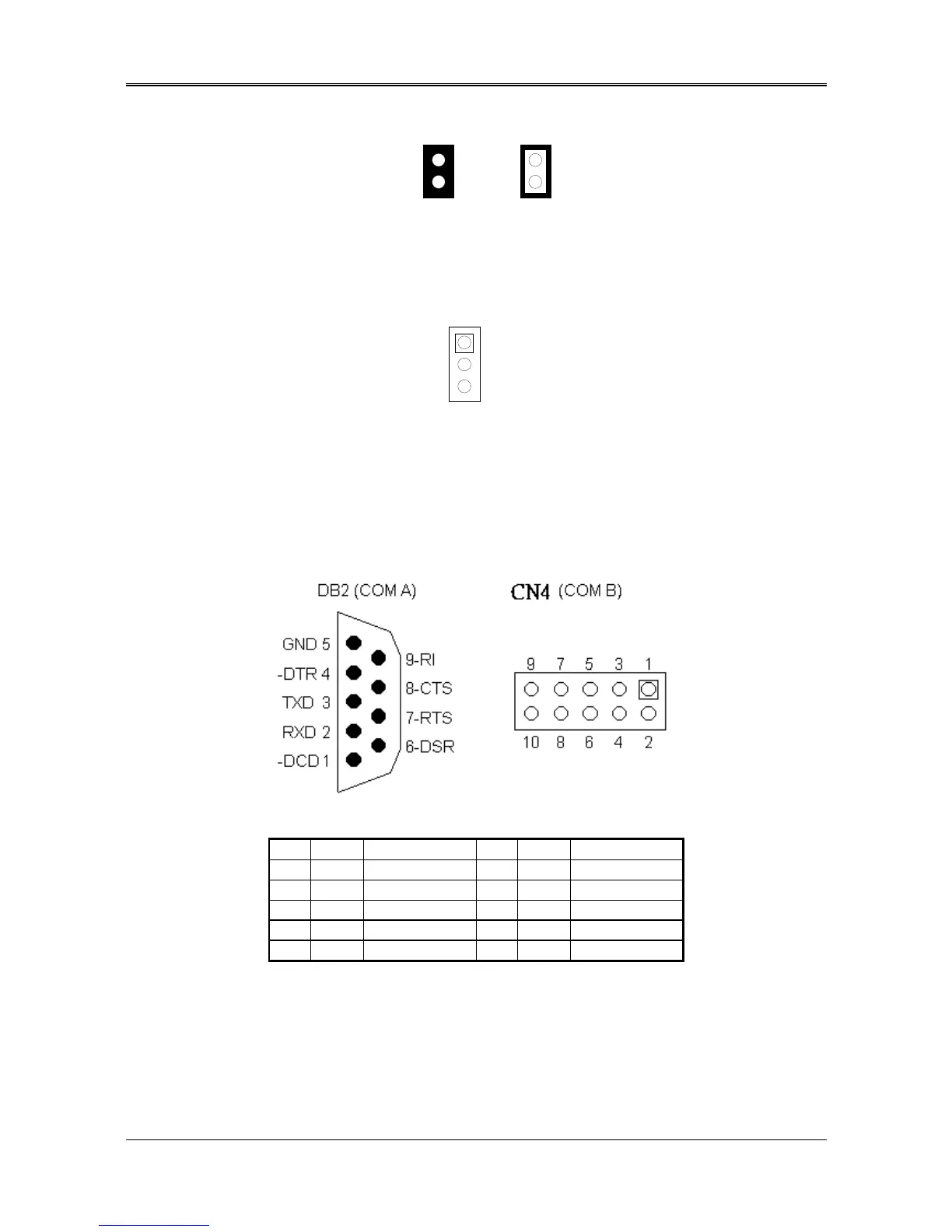
(2) RS-485 Terminator Select (JP1)
OFF
Factory Preset
1
2
1
2
ON
Figure 3-15 JP1: RS-485 Terminator Select
(3) RS-485 Header (J4)
J4 is onboard RS-485 header, J4 pin assignments are as follows:
1 N485+
2 N485-
3 GND
J4 (COM B)
Figure 3-16 J4: RS-485 Connector
(4) RS-232 Connector (CN4 & DB2)
There are two serial ports with EIA RS-232C interface on the AR-B1579. COM A uses one onboard D-type 9-pin
male connector (DB2) and COM B uses one 10-pin header (CN4) which are located at the right side of the card.
To configure these two serial ports, use the BIOS Setup program, and adjust the jumpers on JP1 and JP4.
The pin assignments of the DB2 and CN4 for serial port A & B are as follows:
Figure 3-17 DB2 & CN4: RS-232 Connector
CN3 DB2 Signal CN3 DB2 Signal
1 1 -DCD 2 6 -DSR
3 2 RXD 4 7 -RTS
5 3 TXD 6 8 -CTS
7 4 -DTR 8 9 -RI
9 5 GND 10 -- Not Used
Table 3-5 RS-232 Connector Pin Assignment