ASCON Service Guide Book
43
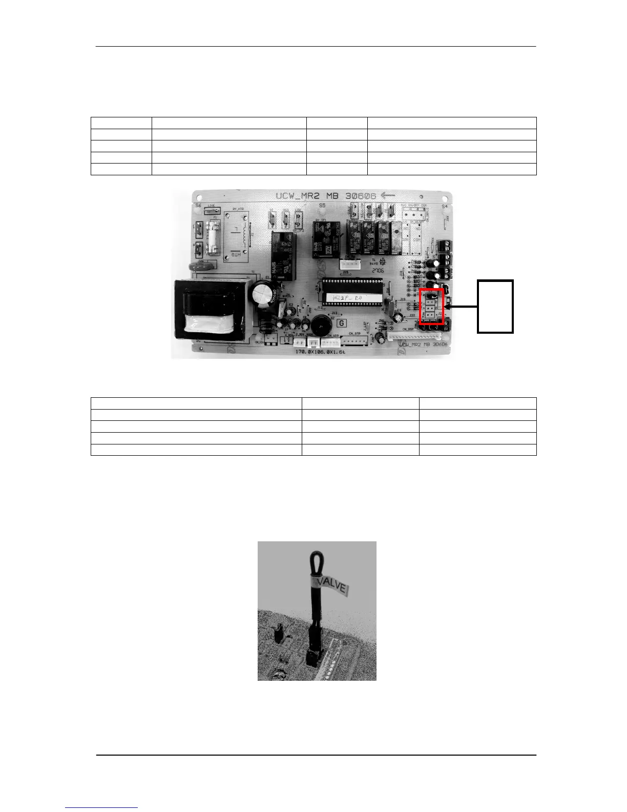
6.7 Chilled Water Fan Coil Unit (W2.0)
The system model can be configured via the following jumpers. For each model selected, the
permissible operating modes are as follows:
Jumper Configuration Model Operating Modes
M1 2 Pipes without Aux. Heater 1 Heat>Cool>Dry>Fan
M2 2 Pipes with Aux. Heater 2 Heat>Cool>Dry>Fan
M3 4 Pipes + Boiler 3 Heat>Cool>Dry>Auto>Fan
M4 4 Pipes + Boiler 4 Heat>Cool>Dry>Fan
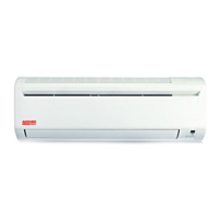
The standard W2 board comes with a VALVE jumper. The system can be configured as the jumper
selection listed below:
VALVE jumper HEAT jumper
Heatpump Mode & Valve Application
√
√
Heatpump Mode & Valveless Application X
√
Cooling Mode & Valve Application
√
X
Cooling Mode & Valveless Application X X
√
: Jumper Remained X : Jumper Removed
VALVE & HEAT Jumper Location
1. VALVE jumper is plugged into JVLV connector on the emergency switchboard.
2. HEAT jumper is plugged into JMODE connector on the emergency switchboard.
M1
M2
M3