eWON4001™
Installation Guide
ver 2.1
page 15 of 31
5.6 Configurable serial port
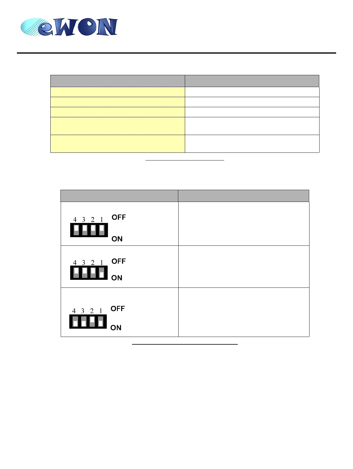
The configuration of the physical serial mode is done by a set of 4 dip switches located on left side from the unit. The
settings of the switches are shown in the table below (note: switch 1 is the most right one).
Note: the 3 switch configurations shown here above are the sole configurations giving satisfactory
results. See important remarks about this configuration on the next page.
Warning: Contrary to indications on the label, the switch 2 is reserved and must stay OFF. Note that
switch 3 & 4 need to have the same position (both ON or both OFF). When they are ON, it
connects the internal polarisation (typ 680 Ohms) and termination (typ 120 Ohms) resistors.
This configuration applies only to RS4xx lines conforming to good practices.
Specification Value
Physical modes (configurable) RS232/RS485/RS422
Normal isolation Non isolated
Optional isolation module (optocoupler) 1 kV
Max serial cable length in non-isolated
configuration
3m
Pinout connector
See label and appendix (Serial Port (optional) on page
28)
Table 11: Serial port specification
Positions Mode
RS232
RS422, RS485
WITHOUT polarisation and termination resistors
RS422, RS485
WITH polarisation and termination resistors
Table 12: Serial mode configuration switches
 Loading...