1A 250VAC
1A 30VDC
0V
DOOR
CONTACT
PUSH
BUTTON
AUX
I
NPUT
RELAY 1
N/C N/O
C
OP2
OP3
S
ENSE
CLOCK
DATA
RED
GREEN
ENTRY/EXIT READER 1
B
0V
T
X
R
X
NETWORK 1
5A 250VAC
5A 30VDC
1A 250VAC
1A 30VDC
5A 250VAC
5A 30VDC
+
CR2032
DOORS
A
B
0V
SERIAL/PRINTER
0
V
D
TR
+
5V
0V
SENSE
CLOCK
DATA
RED
GREEN
ENTRY/EXIT READER 2
+5V
0V
OUTPUTS 1 INPUTS
0
V
DOOR
CONTACT
PUSH
BUTTON
AUX
INPUT
OP2
OP3
OUTPUTS 2 INPUTS
TAMPER
MAINS
PRESENT
+12V DC
AUX RLY 1
N/C N/O
C
R
ELAY 2
N/C N/O
C
AUX RLY 2
N/C N/O
C
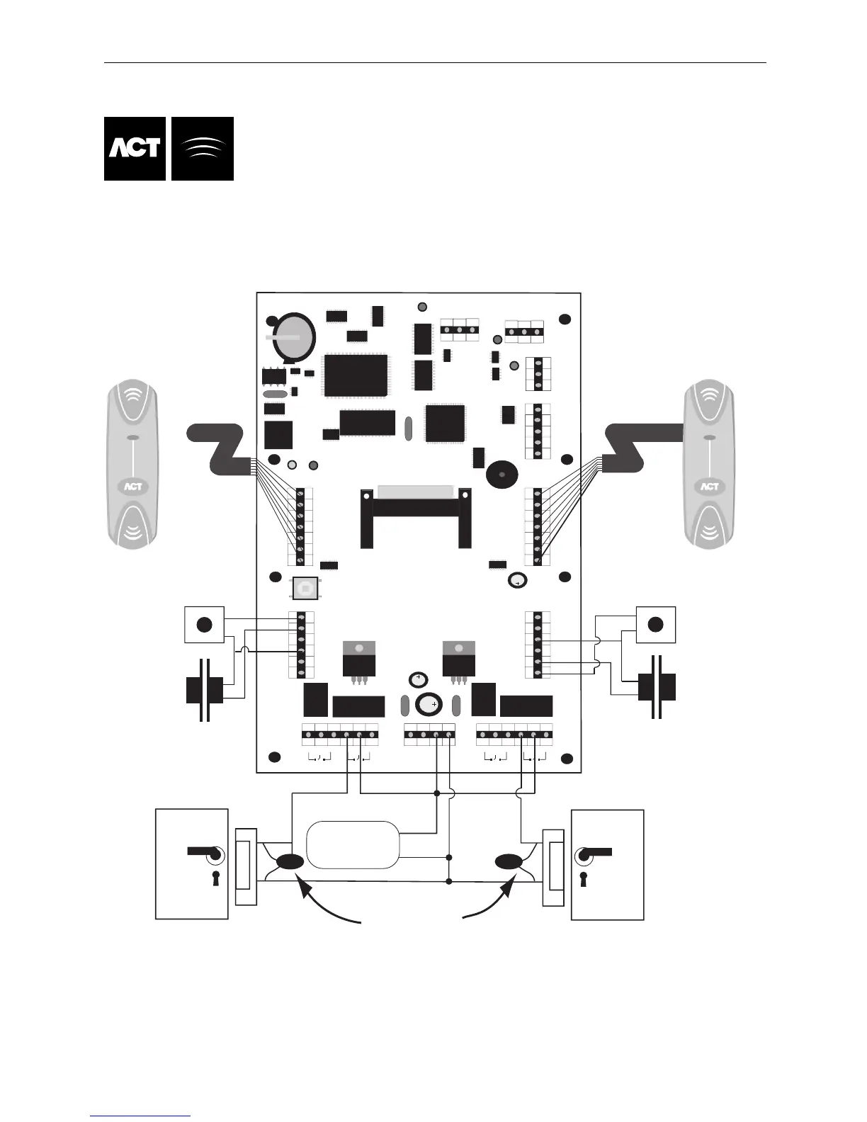
This illustration shows wiring for
normally energised locks.
If normally de-energised locks
are required, use the N/O relay contacts.
Note:
If the Mains Present or Door
Contact inputs are not used,
they should be linked to 0V
Door 2
Release Button
Door 2 Contact
Release Button
Door 1
Door 1 Contact
Card/Proximity or Pin
Reader - Door 2
Card/Proximity or Pin
Reader - Door 1
Important!
Always Place Varistor
Across Lock Terminals
Door 2
Door 1
12V DC
Power Supply
12V
0V
- DC
C
able: 8 Core Screened
Belden 9504 or equiv
Max length 30 Meters
Cable: 8 Core Screened
Belden 9504 or equiv
M
ax Length 30 Meters
T
he Max cable length of
30 meters maybe extended
t
o 100meters, if the reader is
powered from a +12V supply.
B
0V
CTS
Network 2
A
A
Doors
SERIAL/NET1
N
ET2
LINK
TX/RX
Ethernet
Leds indicate activity on NET1/SERIAL, DOORS and NET2
E
thernet Leds
Link Led Indicates connection to Switch/Hub.
TX/RX Indicates reception/transmission or collision.