Disarmed
Alarm Panel
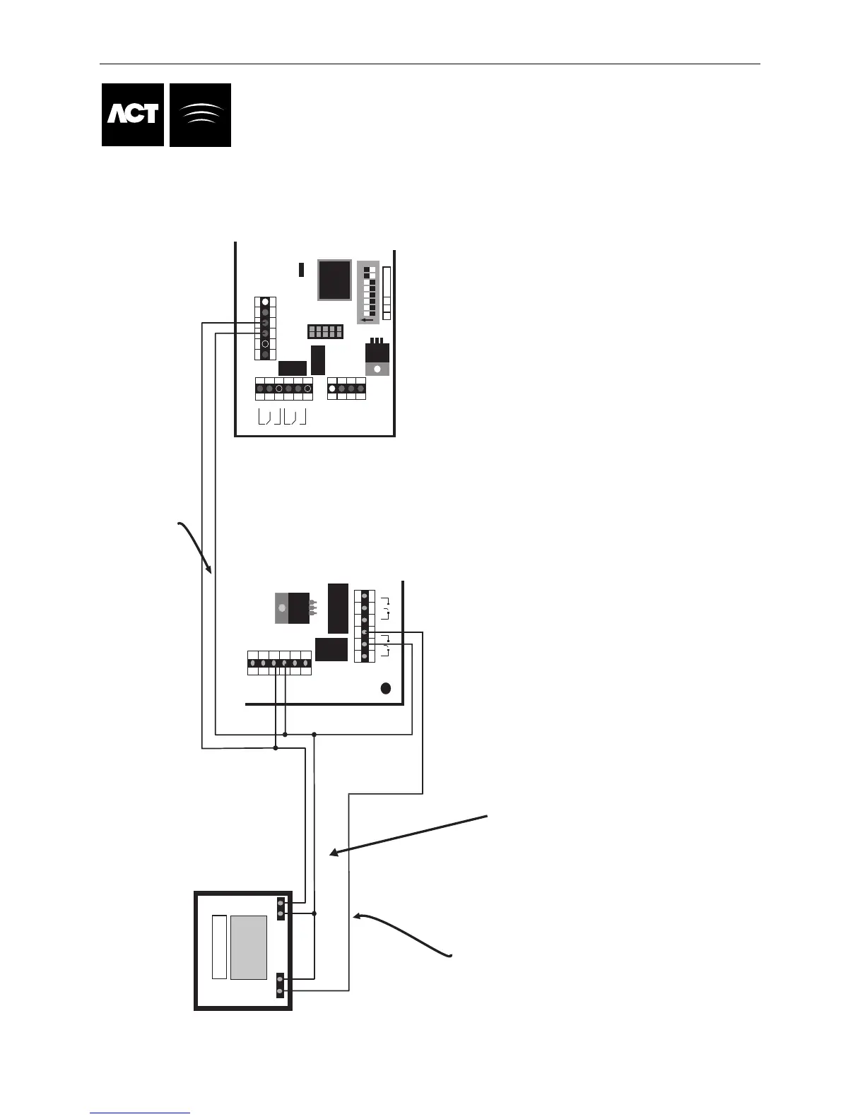
Optional signal from the
alarm panel to indicate armed
or disarmed status. If 0V is
connected to AUX Input,
the panel is armed.
Note:
0V line of ACT Controller
system is connected to
the 0V of the alarm
panel.
Alarm Panel Wiring Diagram
0V
Input
Common the 0V line of
each Controller
While the AUX input is active (connected to 0V), the door is locked.
N/O
COMM
Connect AUX Relay output from controller to
arm input on panel. The AUX relayu can be set to
pulse of toggle. Toggle by programming the AUX
Relay time to zero.
1A 250VAC
1A 30VDC
0V
DOOR
CONTACT
PUSH
BUTTON
AUX
INPUT
RELAY 1
N/C N/O
C
OP2
OP3
5A 250VAC
5A 30VDC
OUTPUTS 1 INPUTS
AUX RLY 1
N/C N/O
C
ACT Controller
DOOR I/O
RELAY
TAMPER
MAINS
+12V
0V
N/C C
AUX RLY
N/ON/C C N/O
5A 250VAC
5
A 30VDC
5A 250VAC
5A 30VDC
PUSH BUTTON
DOOR CONTACT
AUX
0V
OP2
O
P3
1 2 3 4 5 6 7 8
W P 2 Address
On
Door 3
P
age 35 of 37
STEPS TO PROGRAM THE ACT Controller FOR ARM/DISARM
1. Complete the wiring in the diagram above for the door that the system will be Arm/Disarmed from.
2. Enter the installer Menu and select the Door Settings submenu. Then select the Door number
of the reader that User will arm and disarm from.
3. In the Alarm section of Door Settings set the "ARM Intruder" option to Yes.
4. If the Alarm Panel provides a signal to indicated the arm/disarm status then
in the Operation section of the Door settings set the "Monitor Arming" Option to Yes
If the alarm panel does not provide a status signal then ensure the "Monitor Arming"
option is set to No.
5. Exit the installer menu and enter the Operator menu and select "User Settings" chose the
"Assign Options" submenu. Select the User that will be allowed to arm and disarm the panel and
set the option "AUX ARM/DISARM" option bit. Make sure the user is enabled.
6. The configuration is complete. The User can arm the system at the reader by first pressing the "tick" key
followed by presentation of a card. Once the Alarm is armed (as monitored by the AUX IP) the Door will lock.
7. Disarming is achieved by again pressing the "tick" key and presenting the Card.
NOTE: If multiple doors are required to lock when the
alarm is armed, then it is required that each door
monitor the alarm status. If the Alarm is not being
monitored then only the door that is wired to control
the alarm panel will lock.