10
III – DESCRIPTION
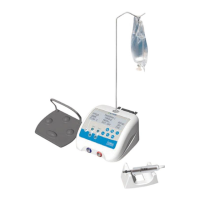
3.1 PHYSICAL DESCRIPTION
-
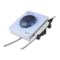
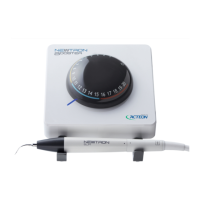
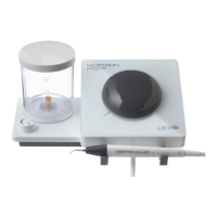
Electronic Control Console (Fig. 1 – 1)
-
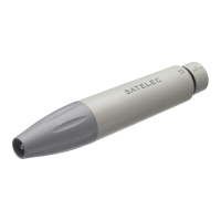
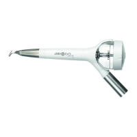
Autoclavable Brushless Micro Motor (Fig. 1 – 2)
-
“Multifunction” Variable-Speed footswitch (Fig. 1 – 3)
-
Motor Holder (Fig. 1 – 4)
-
Bracket (Fig. 1 – 5)
-
Peristaltic pump tube (Fig. 1 – 6)
-
Power Cord with external transformer (Fig. 1 – 7)
Note: All accessories are supplied non-sterile with the exception of tubing
3.2 TECHNICAL DESCRIPTION
a. LCD screen/control Keypad
The I-SURGE is adjusted by applying reasonable pressure to the keypad buttons.
-
Motor ON/OFF (Fig. 2 – 1)
-
Pump ON/OFF (Fig. 2 – 2)
-
Pump flow adjustment (Fig. 2 – 3)
-
Storage and quick access up to 5 different “Programs” (implant configurations) (Fig. 2 – 4)
-
Speed Increase/Decrease (Fig. 2 – 5)
-
Torque adjustment (Fig. 2 – 6)
-
Handpiece ratio selector (Fig. 2 – 7)
-
Forward/Reverse Selector (Fig. 2 – 8)
-
Handpiece calibration (Fig. 2 – 9)
-
Motor Receptacle (Fig. 2 – 10)
-
Footswitch in (Fig. 2 – 11)
Information required by the user is displayed on the LCD screen.
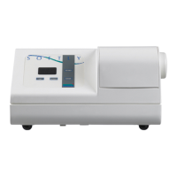
b. Control unit back panel
-
Irrigation pump housing and irrigation tube insertion (Fig. 3 – 1)
-
Mains cord in (Fig. 3 – 2)
-
Main Power On/Off Switch (Fig. 3 – 3)
-
Fuses and voltage selector (Fig. 3 – 4)
c. Control footswitch
- Switching the coolant pump flow (Fig. 4 – 1)
- Switching Programs (Fig. 4 – 2)
- Clockwise/Anticlockwise running (Fig. 4 – 3)
- Smooth variation of the speed up to the pre-selected maximum (Fig. 4 – 4)
- Arch (Fig. 4 – 5)