Doc. No.0525-077 Ver. 2 200129
SRD175C / SRD175E
TECHNICAL & SELECTION DATA
UNIT FEATURES
Digital Scroll Compressor•
10-100% Variable Refrigeration Capacity•
Multiple Speed Outdoor Fans•
Louvre Outdoor Coil Guard•
Pre-charged with R410A Refrigerant•
AM7-D8 Wall Controller Supplied as Standard•
20 m of Data Cable Included•
EXV (Electronic Expansion Valve)•
Integral Fan Coil Safety Tray with Drain Kit •
Indoor Coil Overheat Protection•
Indoor Coil Anti-Freeze Protection•
Smart Defrost Function•
CONTROL FEATURES (AM7-D8)
7-Day Programmable Controller with 2 Events/Day •
24- Hour ON/OFF Timer•
Auto, Heat & Cool Modes•
Auto/Continuous Indoor Fan Operation•
3 Speed Indoor Fan Setting•
Hot Start Feature•
Home/Building Automation ON/OFF Capability•
CONTROL OPTIONS
Remote Temperature Sensors•
Zone Kit for Control up to 8 Zones •
(See Integrated Zones, Barrels & Plenums Section)
Secondary Wall Controller with Mimic Logic•
PLENUMS (Optional)
Supply Air Plenums are Available in a 2 way or 3 way•
Confi guration (See Integrated Zones, Barrels and Plenums
Section for details of Spigots availability)
Return Air Plenums are Available with 2 x 400 mm Spigots • or
2 x 450 mm Spigots
SPECIFICATION SUMMARY
TOTAL * NETT **
COOLING CAPACITY (kW) *** 18.12 17.40
SENSIBLE CAPACITY (kW) *** 14.81 14.09
HEATING CAPACITY (kW) ^ 17.60 18.30
COOLING INPUT POWER (kW) ^^ 6.07
HEATING INPUT POWER (kW) ^^ 5.44
EER 2.99 2.87
COP 3.24 3.37
INDOOR AIRFLOW (l/s) -- MIN. / NOMINAL / MAX. ^^^ 740 / 920 / 1100
OUTDOOR SOUND PRESS. LEVEL @ 3M dB(A) -- LOW / HIGH 52.0 / 54.0
OUTDOOR SOUND POWER LEVEL dB(A) -- LOW / HIGH 69.0 / 71.0
POWER SUPPLY - OUTDOOR 240 V / 1 Ph / 50 Hz
POWER SUPPLY - INDOOR 240V / 1 Ph / 50 Hz
RATED LOAD AMPS -- OUTDOOR / INDOOR / TOTAL ** 22.0 / 3.1 / 25.1
FULL LOAD AMPS -- OUTDOOR / INDOOR / TOTAL ^^^^ 32.6 / 4.0 / 36.6
CIRCUIT BREAKER AND CABLE AMPS
40.0
APPROXIMATE STARTING AMPS <45.0
WEIGHT (kg) -- INDOOR / OUTDOOR 75.0 / 180.0
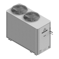
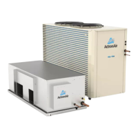
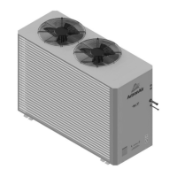
OUTDOOR UNIT MODEL SRD175C
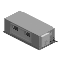
INDOOR UNIT MODEL SRD175E
Based on unit rating excluding indoor fan kW.
Measured and tested in accordance with AS/NZS 3823.1.2.
At 27
0
C DB / 19
0
C WB entering air temperatures and 35
0
C ambient.
At 20
0
C DB entering air temperature and 7
0
C DB / 6
0
C WB ambient.
Input power includes indoor fan kW.
Max. - Min. airfl ow application range.
Full Load Amps are based on Compressor and Fan Motors’ maximum expected current.
See Specifi cations sheet for Cable Size and Circuit Breaker Size details.
Note: Use input power to estimate running cost.
*
**
***
^
^^
^^^
^^^^
ActronAir is constantly seeking ways to improve the design of it’s products, therefore specifi cations are subject to change without notice, Please check prior to purchase.
SRD175C-0100 / SRD175E-0100 -P1- 090326
R
R410A
DIGITAL SCROLL
COMPRESSOR
ESP SPLIT DUCTED UNIT
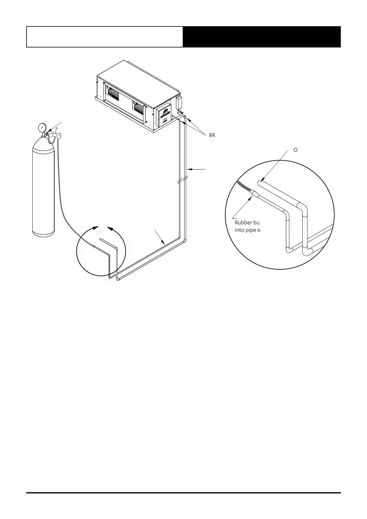
1. Run interconnecting pipe work from condenser location to evaporator.
2. Release pressure in evaporator and remove caps.
3. Fit copper tube into tail, set nitro bottle and regulator up at condenser end of pipe work.
4. Fit nitrogen line into liquid line with rubber bung to seal the connection. The seal will prevent air being sucked into
pipe work.
5. Leave suction line open, set nitro regulator for nitrogen to flow through pipe work at 2 l/s flow rate @20kPa.
6. Braze required joints as quick as possible.
See Diagram Above.
1. Starting with circuit 1 system, remove piping caps from the condenser and fit pipe work into tails.
2. Fit nitro hose onto suction ball valve and fit open hose onto liquid line post valve.
3. Set nitrogen regulator to 2 l/s flow rate through pipe work and evaporator.
4. Braze remaining joints as quick as possible.
5. Allow the brazed joints to cool and conduct leak test in the connections.