Installation and Commissioning Guide - Split Ducted ESP Digital Units
Doc. No.0525-077 Ver. 2 200129
Installation and Commissioning Guide
Split Ducted ESP Digital
24
11. Electrical Installation
All electrical work must be carried out by a qualified and licensed technician. Make sure all wiring is in accordance with
local wiring rules. Wiring connections should be made in accordance with the wiring diagram provided.
DANGER
Live Electrical Supply !
During installation of your air conditioning unit, it may be necessary to work in close proximity to live electricity. Only
licensed electricians are allowed to perform these tasks.
Follow all electrical safety precautions when exposed to live electrical components.
Wiring Diagram
The wiring diagram specific for your air conditioning system is located on the inside panel of the control access door.
Always refer all wiring installation, servicing and troubleshooting of this equipment to this diagram to ensure correct
electrical connection are satisfied.
Supply and Power Requirements Procedure
It is the installer’s responsibility to provide power supply wiring to the mains supply terminal strip of the outdoor unit.
Make sure all wiring are in accordance with local wiring rules. Wiring should conform to all current electrical authority
regulations and all wiring connections to be as per electrical diagram provided with the unit.
• Confirm that the power supply available is compatible with the unit nameplate ratings. The supply power must be
230V/400VAC(+/- 6%)/50Hz.
• Protect electrical service from over current and short circuit conditions in accordance with AS/NZS 3000
“Australian / New Zealand Wiring Rules”. Size protection devices according to the electrical data of the unit and the
table below.
• Installer to connect an appropriate load break (AC3) isolator in sub mains wiring.
• Secure any power and control cables that enters in/exits out of the unit. Use the cable ties provided in the main
electrical panel.
• Complete the unit power supply wiring onto the main isolator.
• Secure the power cords and control cables that goes in/out the unit. Use the cable ties provided in the control box.
• Provide proper unit earth in accordance with local and national codes.
Main Voltage Balance Requirement
Check the voltage at the mains supply terminals to determine if it is balanced. Voltage imbalance on three phase
systems can cause motor overheating and premature failure. The maximum allowable imbalance is + 2.0%, should
voltage imbalance exceed this value, check unit wiring connections to locate and rectify faults or contact local supply
authority.
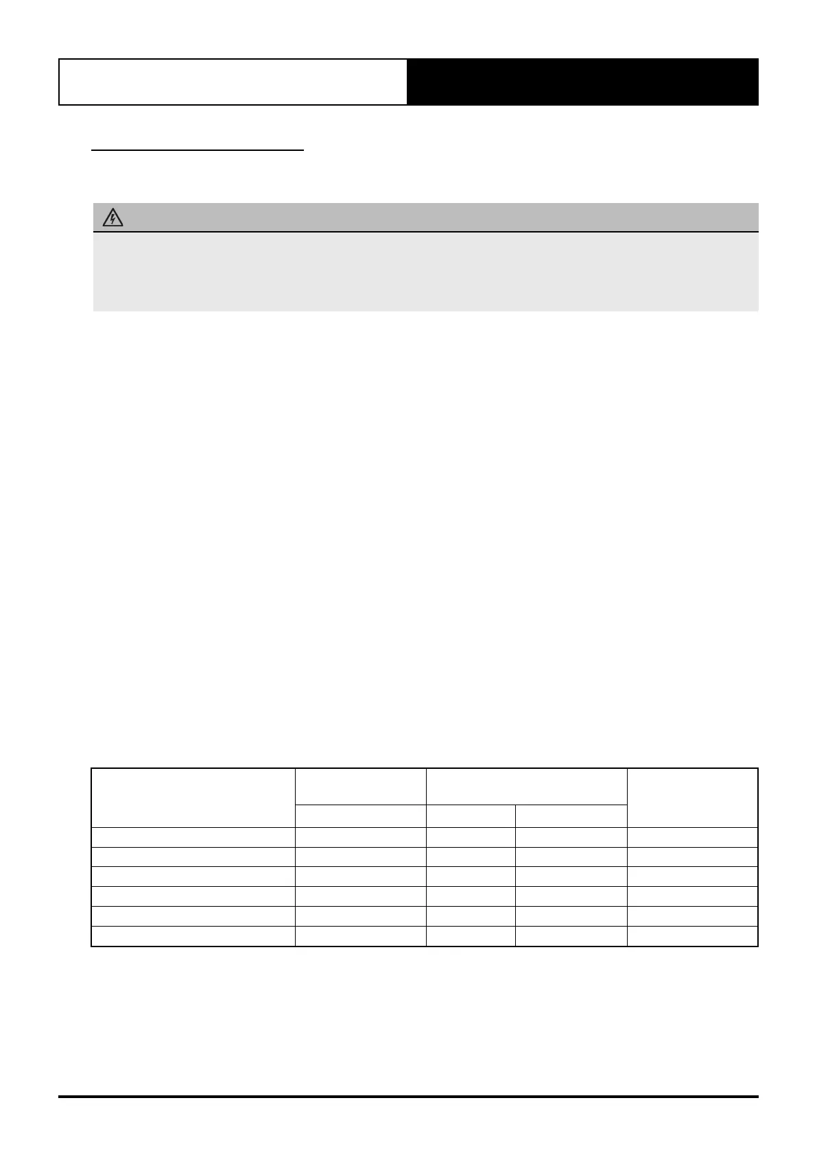
MODEL
Circuit
Breaker Size
Cable Size * (mm)
Wiring Diagram
Amps MAIN O.D. to I.D.
SRD131C / SRV131E 32.0 6.0 1.0
WD0870
SRD151C / SRV/M151E 32.0 6.0 1.0
WD0870
SRD191C / SRV/M191E / SRV191F 40.0 10.0 1.0
WD0870
SRD173C / SRV/M171E 20.0 2.5 1.0
WD0871
SRD203C / SRV/M201E / SRV201F 20.0 2.5 1.0
WD0871
SRD233C / SRV/M231E 25.0 4.0 1.0
WD0872
* Suggested Minimum Cable Size should be used as a guide only, refer to AS/NZS 3000 “Australian / New Zealand Wiring
Rules” for more details.