© ADB SAFEGATE All Rights Reserved
15
2.4.2 Connection to the Ethernet Network
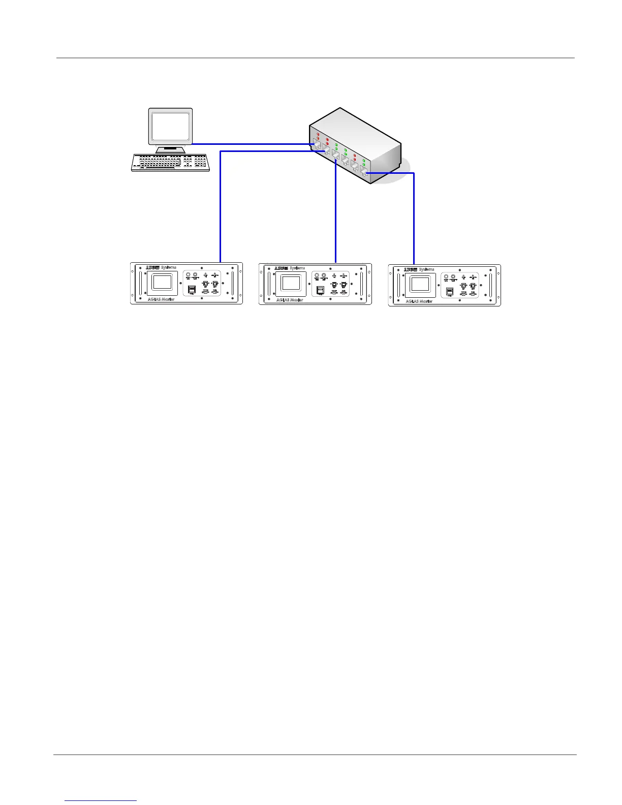
Figure 8: Ethernet connections
The AGLAS Master is to be connected via a shielded CAT5 network cable, with RJ45 plugs to the ETH-0 port and the hub or switch
of the Ethernet network. The cable is to be run as a 1:1 connection or Eth-1.
The usual segment length restrictions for Ethernet networks apply.
(For the location of the Ethernet connectors: refer to “Front View with Control Unit” on page 9).
2.4.3 Earth Grounding
To protect the devices against surges that could be caused by a lightning strike, each AGLAS Master is to be earth ground
separately via the earth ground screw, with minimum induction or resistance. For this an earth ground cable with a suitable cable
lug is to be fixed to the earth ground screw on the AGLAS Master (M6 screw thread). The cross-sectional area of the cable should
be at least AWG 8 (6mm
2)
with a maximum cable length of 39” (1m).
All masters ground terminals must be connected to a common earth grounded bar in the vault or substation.
(For the location of the earth ground screw: refer to “Rear View with Connections” on page 11.)
Eth0 Eth0
Eth0
AGLAS PC
TCP/IP Network
switch with
IEEE1588 PTP
AGLAS Master 1 AGLAS Master 2 AGLAS Master 3
TCP/IP 1Gbit/s
TCP/IP 100Mbit/s
TCP/IP 100Mbit/s
TCP/IP 100Mbit/s
AGLAS Master 1 AGLAS Master 2
AGLAS Master 3