AGLAS Master Control Device
Theory of Operation
© ADB SAFEGATE All Rights Reserved
12
96A0480 Rev. B
2.2.8 Operation
2.2.9 Circuit Specifications
Cable type L-824 is recommended, for example FLYCY or equivalent. The following parameters (*) represent the specific
characteristic needed in an equivalent L-824 cable. Reuse of existing installations and layout with maximum cable length or
number of lights to be verified.
* Contact ADB Safegate for support
** Technical requirement, not excluding ICAO /FAA compliance
2.3 Theory of Operation
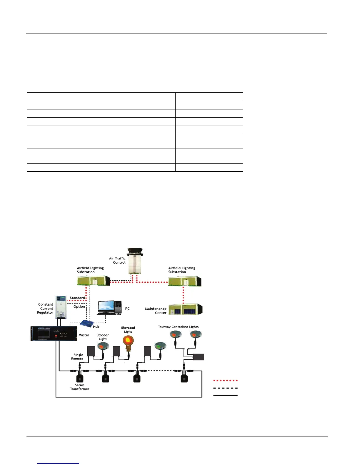
Background Information: AGLAS uses power line carrier (PLC) technology to communicate between controlling units on an airfield
lighting series circuit. A AGLAS system typically consists of one high voltage modem, or Master, collocated with the Constant
Current Regulator (CCR) powering the airfield lighting circuit and many slave units, or Remotes, collocated with individual lights in
the field. A typical AGLAS topology is provided in Figure 6.
Figure 6: Typical AGLAS Topology
2.3.1 Main Characteristics and Figures
•
Up to 300 Remotes per circuit, providing a potential of 600 individually addressable lights per circuit.
Cable type (specification) L-824
Capacity of the cable <165 nF/km *
Inductance of the cable <0.20 mH/km *
typical impedance (125 kHz) 35 Ohm
Attenuation of the signal at 125 kHz <5.8 dB/km *
Length of serial circuit
20 km roundtrip (12.4 miles)
maximum
Insulation resistance of the series circuit against the L-824
shield or ground
50 Megaohms minimum **
Secondary transformer attenuation ≤ 23 dB at 100 kHz *
Legend
Commands from ATC (Fiber Optic)
Field communication (Ethernet)
Power line
Dual
Remote