© ADB Airfield Solutions All Rights Reserved 15
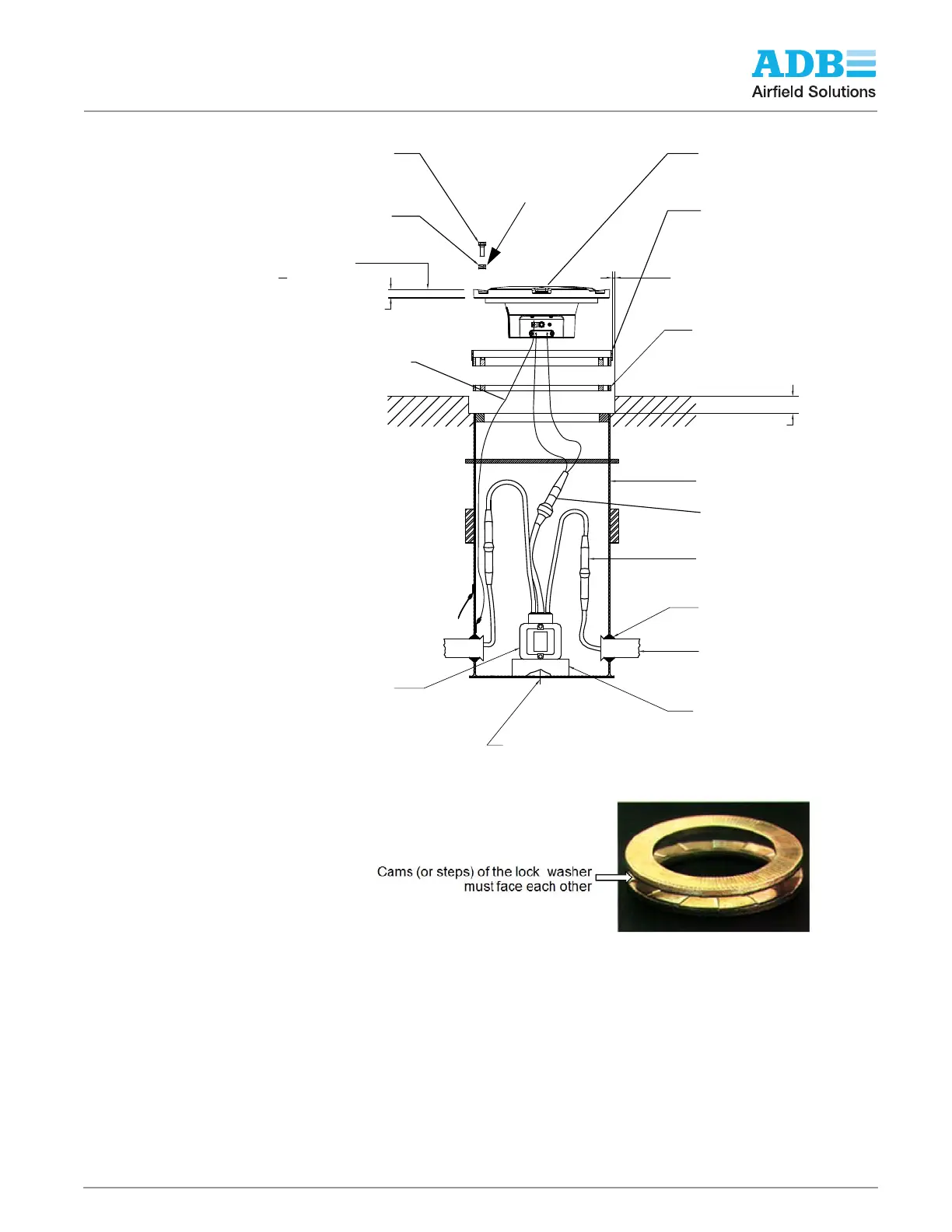
Figure 5: Diagram of the Fixture Installed in a 1-Piece Base Can
NOTE:
The cams (or steps) of each half of the lock washer must face each other.
NOTE: Per FAA AC 150/5340-30, Chapter 10, and FAA Engineering Brief No 83, it is
extremely important that other types of washers, such as split washers, must not be used.
Failure to use properly installed anti-vibration lock washers will cause mounting bolts to
become loose.
1-1/2" (TYP.)
1/4" WIDE X 1-1/2" DEEP GROOVE (TYP.)
L868B FLANGE RING 12.25" O.D.
3/4" THICK, 5402/12Y
WITH O-RING GASKET (TYP.)
SEMI-FLUSH
LIGHT FIXTURE
TYPE L-85X (TYP.)
NORDLOCK NL 3/8 2 PIECE LOCKWASHER OR EQUAL
3/8-16 STAINLESS STEEL BOLT
(TYP. OF 6)
0.75"
GROUND WIRE
6AWG
L868B LIGHT BASE
L-823 PRIMARY CONNECTOR
(TYP.) (HEATSHRINK OPTIONAL)
GROMMET
TRANSFORMER SUPPORT
(TYP.)
ISOLATION TRANSFORMER
SIZE AS REQUIRED
L868B SPACER RING(S)
2" PVC CONDUIT W/BELL END
3/4" DRAIN HOLE (CENTERED)
FIXTURE TOP EDGE TO BE
+0/-
1
16 " BELOW GRADE
L-823 SECONDARY CONNECTOR
In order to maintain +0/- 1/16” below grade, per FAA installation tolerance,
a maximum of 3 spacers may be used.
See notes
below
Torgue according to: “Installation on
L-868 Base” on page 16
 Loading...