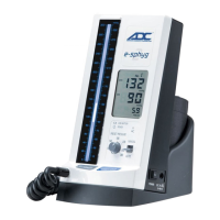
11
1. Securely attach wall bracket to flat surface using en-
closed mollys and screws at desired height.
(It is advised to use a level to ensure proper mounting)
. (Figure 1)
2. Attach manometer to wall bracket by lowering a top wall
bracket, sliding male tab into female seat of the bracket.
Secure the two together using the (6mm) allen bolt and
washer from below. Tighten securely with large (6mm)
allen wrench (Figure 2).
3. Securely attach cuff basket to flat surface to left of
manometer using enclosed mollys and screws at desired
height.
(It is advised to use a level to ensure even mounting)
(Figures 3 - 4).
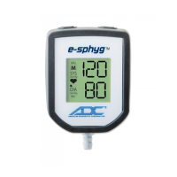
4. Attach 8 foot length coiled tubing to air inlet on face of
e-sphyg
TM
2 (Figure 5).
Insert “male” luer connector (891M) on free end of
coiled tubing to “female” luer connector (891F) on
bladder tubing (Figure 6). Fold cuff and store in basket.