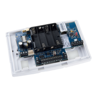
IRIS-4 Technical Reference Manual.docx 12/01/2023 page 11
3.3 The 4xx
Sys LED indications
LED Color Indication
Yellow
flashing
Not currently configured or indicating there are current
faults outstanding. See section 9.1, “Trouble report”.
Yellow
constant
Communicating and no current faults (flickers on every poll).
Expansion boards
An expansion board can be added to the 4xx main board. There are 3 variants:
EXT1: provides additional 12 pin inputs.
EXT2: provides additional 12 pin inputs and a standard PSTN analog line interface (PSTN) as an outbound
transmission path for alarms.
EXT3: provides an additional 12 pin inputs and 3 mechanical relays (EXT3 not supported on 4xxG boards)
See section 4.2.1 “Installing the Extension boards on the 4xx” for installation instructions.
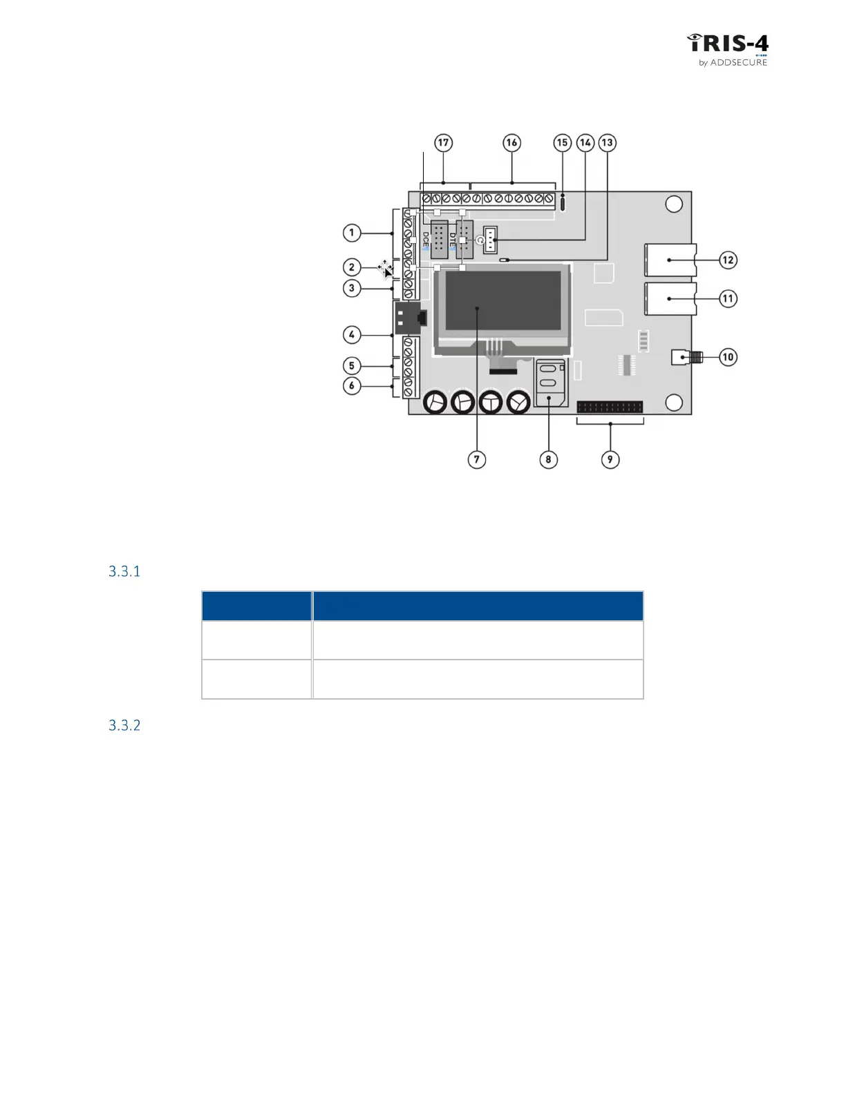
①
= 2 x RS232 screw terminals
②
= CAN bus (not supported)
③
= RS485 screw terminals
④
= Dial capture port, RJ45 &
screw terminals
⑤
= External tamper screw terminals
⑥
= DC power screw terminals
⑦
= Touchscreen
⑧
= SIM card holder
⑨
= Expansion board connector
⑩
= Cellular antenna socket
⑪
= Ethernet 1 connector
⑫
= Ethernet 2 connector
⑬
= Sys LED
⑭
= Serial (TTL) connector
⑮
= Micro USB connector
⑯
= Relay outputs screw terminals
⑰
= Pin input screw terminals
⑱
= 10-way headers for full RS232
connection
⑱