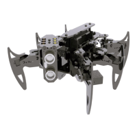
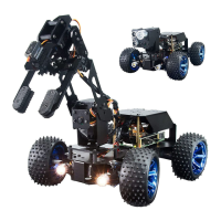
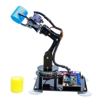
Effect diagram after assembling
The connection diagrams of the remaining modules and wires are as follows:
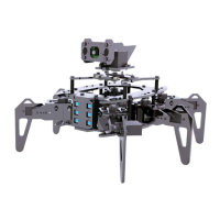
3. Screw the M4*4 Locking Screw into the S12D4 Coupling (2 sets).
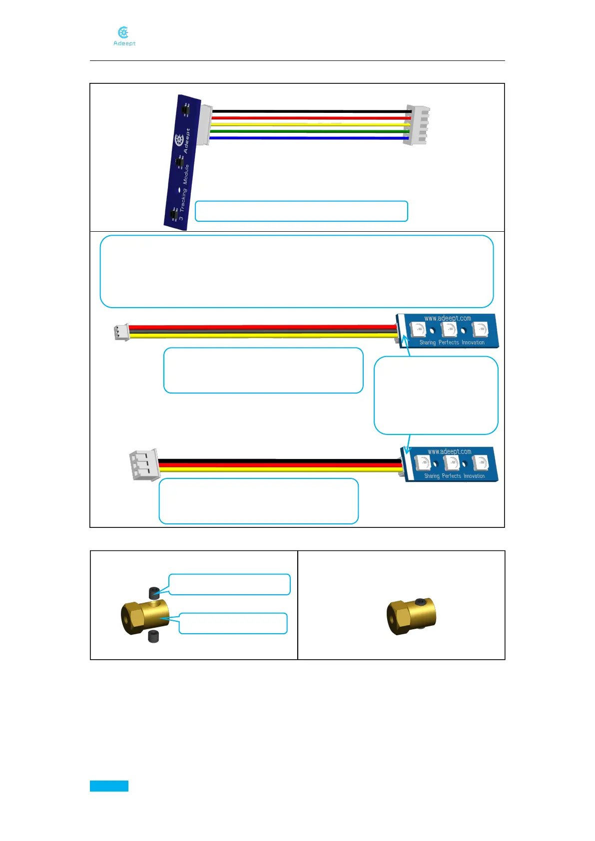
3 Tracking Module+5-Pin wire 1 set
The two plugs of 3-Pin Wire-A are small plugs, 3-Pin Wire-B has a small plug at one
end and a large plug at the other end. To prevent confusion between the following
two components when reading the manual, we define the following two components
as Car Light-A and Car Light-B.
Car Light+3-Pin Wire -A 3 sets
Defined as Car Light-A
Wires are connected to
the input of Car Light (the
end marked with a white
strip pattern)
Car Light+3-Pin Wire -B 1 set
Defined as Car Light-B
Assemble the following components