SET COMMUNICATION:
This section define the fundamental communication parameters of two buses, PROFINET and J1939.
By Pressing the “Set Communication” button from the main window for SW67610 (Fig. 2) the
window “Set Communication” appears (Fig. 3).
The window is divided in two sections, one for the PROFINET and the other for the J1939.
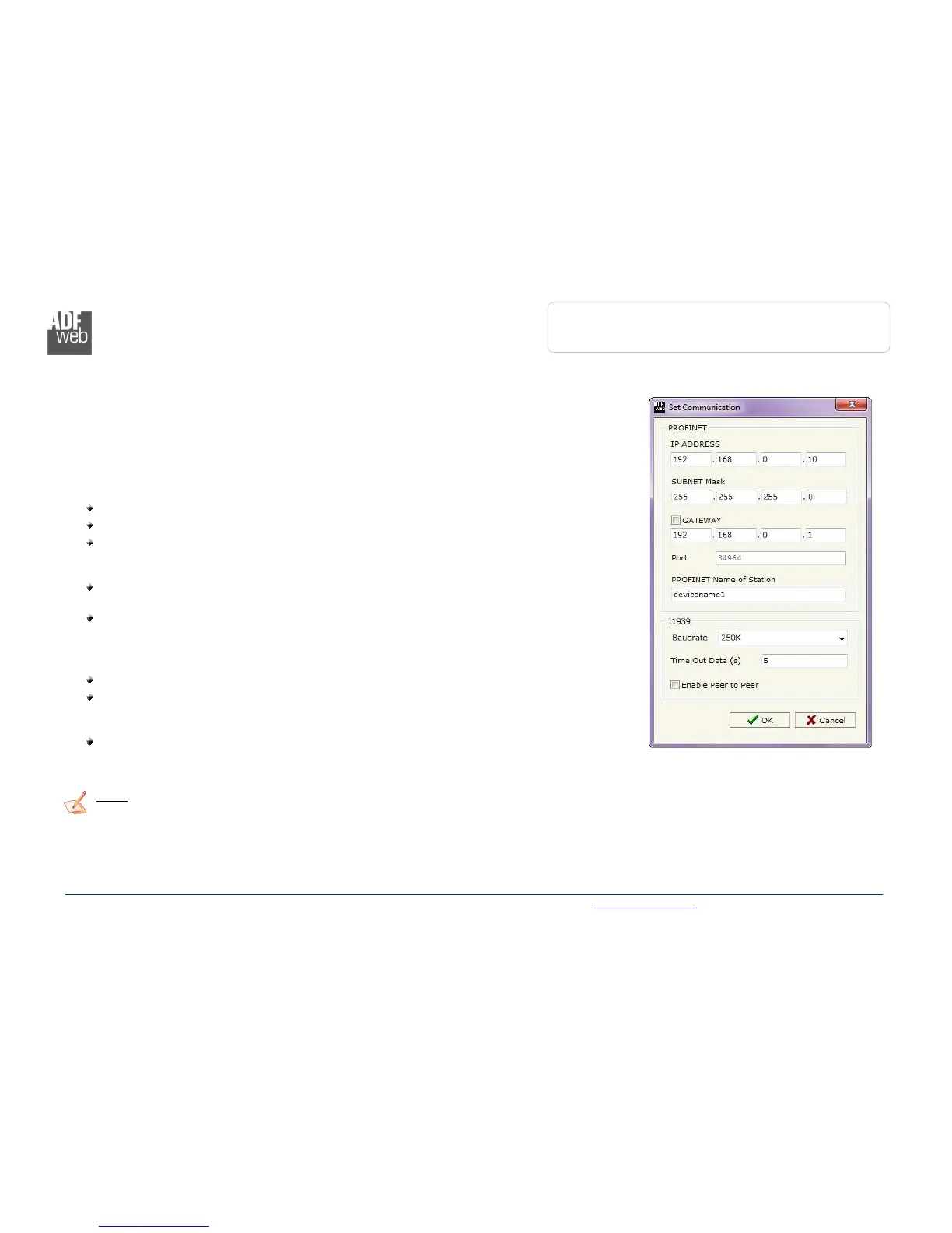
The means of the fields for “PROFINET” are:
In the fields “IP ADDRESS” insert the IP address that you want to give to the Converter;
In the fields “SUBNET Mask” insert the SubNet Mask;
In the fields “GATEWAY” insert the default gateway that you want to use. This feature can
be enabled or disabled pressing the Check Box field. This feature is used for going out of the
net;
In the field “Port” the port used for PROFINET communication is defined. The port has a
fixed value of 34964;
In the field "PROFINET Name of Station" is possible to assign a name to the PROFINET
node.
The means of the fields for the “J1939” section are:
In the “Baudrate” field the J1939 baudrate is defined;
In the field “TimeOut Data” insert a time; when this time is elapsed and the data isn’t
reliable, in the PROFINET data array you read “0”. It is possible to use this function only for
the “Receive Frames”;
If the field “Enable Peer to Peer” is checked, the gateway accepts all the ID that have the
PGN inserted in the “Receive Frames” section.
Note:
The number of Input byte and Output byte of PROFINET is calculated automatically by the Compositor in relation of the J1939
frames defined.
Figure 3: “Set Communication” window