10
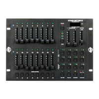
FRONT PANEL CONTROLS AND FUNCTIONS
1. CHANNEL LEDS (1-8): These 8 LEDs control intensity for channel sliders 1-8. Moving the slid-
ers upwards increases the output. LED indicators directly reect changes in slider level.
2. SCENE X - CHANNEL FADERS 1-8: These 8 sliders are used to control the intensities of chan-
nels 1-8. The overall intensity of channels faders 1-8 is controlled by the X Crossfader (5).
3. MODE BUTTON: This button is used to change the unit’s operating mode. There are 3 different
operating modes to choose from: 2x8, 8x8, and 1x16. The unit’s current operating mode will indi-
cated by an LED that corresponds to the operating mode icons. Mode operations are explained
in the General Operation section of this manual.
4. RECORD BUTTON: This button is used to activate the unit’s record mode. You may create up to
eight of your own programs, which are then stored on the Chase Buttons (17). Refer to the Basic
Programming section of this manual. When the Record Button is depressed, the record LED will
begin to glow, indicating that Record Mode has been activated. Once Record Mode is activated,
you may begin to program chase patterns or static scenes into the eight user Chase Buttons
(17).
5. X CROSSFADER: This slider controls the overall intensity of the Scene X channel faders (2).
The X (5) and Y (6) faders allow crossfading between Scene X (2) and Scene Y (11) The X
Crossfader is at its maximum intensity while in the full up position. In 1x16 mode, the X Cross-
fader controls the intensities of channels 1-16.
6. Y CROSSFADER: This slider controls the overall intensity of the Scene Y channel faders (11).
The X (5) and Y (6) faders allow crossfading between Scenes X (2) and Scene Y (11). The Y
Crossfader is at its maximum intensity while in the full down position. In 1x16 mode, the Y Cross-
fader controls the scene Fade Time. The offset conguration of the X (5) and Y (6) crossfaders
allows easy dipless crossfading between scenes, when both crossfaders are moved together.
7. LCD DISPLAY: This multifunctional display will detail the unit’s current operation. The LCD will
indicate an active MIDI signal by ashing an LED next to the MIDI icon.
8. MASTER LEVEL SLIDER: This slider controls the overall channel intensity levels for channel
sliders, 1-16 (2 & 11), and will also control the master intensity level for programs 1-12 (12 & 17).
This slider will have no effect on the Full On (14) and Bump (10) functions. For example: When
the Master Slider is at minimum, all output will be zero, except for any resulting from the Bump
Buttons (10) and Full On Button (14). Zero output will be indicated by the LCD Display (7), again
with the exception of any output resulting from the Bump Buttons (10) and Full On Button (14). If
the slider is at 50%, all outputs will be at 50%. The LCD (7) will display 50% output. If the slider is
at 10, all outputs will be 100%. This will be indicated by 100 in the LCD Display (7).
9. CHANNEL LEDS (9-16): These 8 LEDs indicate the current intensity for channel sliders 9-16.
Raising the channel slider will increase the output. The LED indicators will directly reect the
changes in slider level.
10. BUMP BUTTONS: Each of the eight Bump Buttons can be programmed to control a single chan-
nel or a group of channels (1-16). The eight buttons can then be used to bring an individual or
group of channels to full intensitym, and override the Blackout (15) function or the Master Level
(8) setting. In 1x16 mode, each button can be programmed to control a group of channels, ef-
fectively making each button a Flash Scene. The Bump Buttons are also used in programming
mode, when programming Flash Scenes and Master Scenes.
11. SCENE Y: These 8 sliders are used to control the intensities of channels 9-16 (11). The overall
intensity of channel faders 9-16 (11) is controlled by the X Crossfader (5).
12. BUILT-IN CHASES 9-12: These four buttons are used to activate any of the four built in pro-
grams stored in the unit’s memory. A chase LED will glow when a corresponding chase has been
selected for operation.