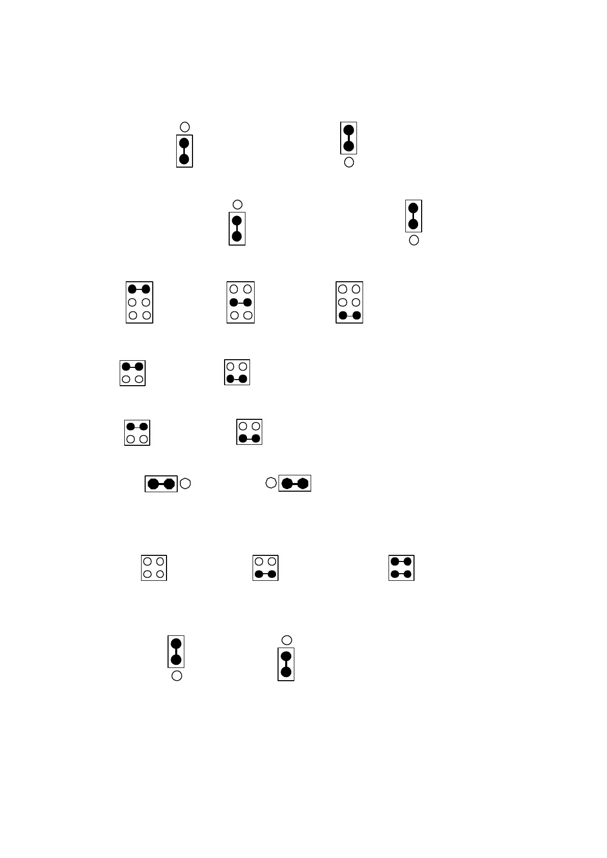
Jumper setup-MS4-307~322
1. JP1 : VR on panel / VR on F306
VR on panel VR on F306
2. S1 : MB / CF3 selection
2 and 3 short CF3→ 1 and 2 short CF3→
Running relay MB 5-8th speed terminal
(Refer Example 04)
3. J4 : RST / FT2 / CF2 selection
RST FT2 CF2
4. J5 : FT1 / CF1 selection
FT1 CF1
5. J3 : ARR / MET selection
ARR MET
6. J10 : Fault A / Fault B terminal
Fault A Fault B
7. J7
0~10V 0~5V 4~20mA
8. JP2 : MET output signal selection
Meter Analog
0~10VDC
Meter : Connect meter + to terminal H and meter - to terminal MT.
0~10VDC : Terminal MT is + and Terminal GND is -.
15