612877GONT-22B 3
3. Remove the rubber grommet from the housing and insert the power
and ground cable through the grommet.
4. Terminate the two UPS power leads (Pins 6 and 7) and, if needed,
the five alarm status leads in the power connector.
5. Reconnect the Power/Alarm Connector to the bottom of the
Electronics Module.
6. Tie Wrap the wires through the holes just below the Power/Alarm
connector.
7. Replace the rubber grommet while closing the Electronics Module.
This places less stress on the wiring and allows the Electronics
Module to close without pinching any wiring.
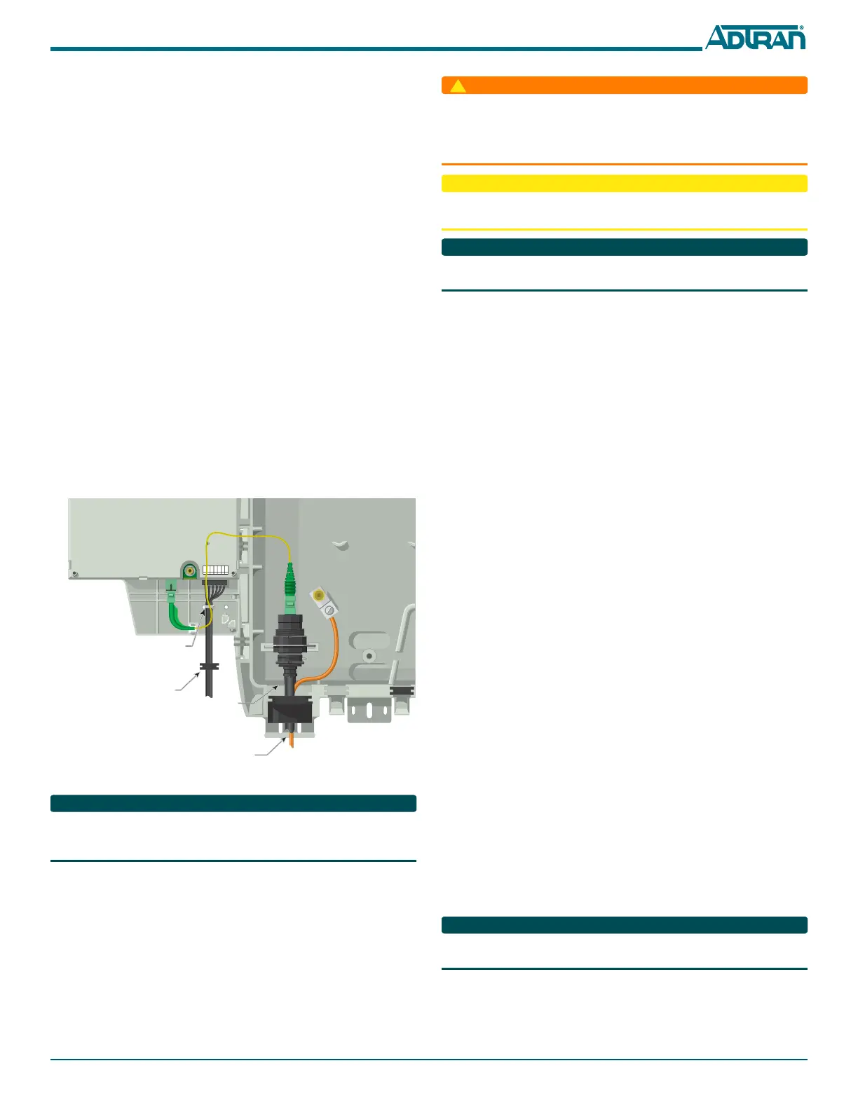
Route the OptiTap Fiber Drop Cable, Outdoor ONT
Refer to Figure 5 for fiber installations:
1. Place the OptiTap fiber drop in the same rubber grommet channel
as the ground cable. The ground cable should be “behind” the Opti-
Tap fiber.
2. Clean all optical surfaces before and after splicing.
3. Splice the incoming fiber to the OptiTap connector using a Fusion
Splice.
4. Clean the optical surfaces and connect the OptiTap fiber.
5. Place the OptiTap connector in the cut-out in the housing.
6. Connect the fiber cable to the connector on the bottom of the
Electronics Module.
7. Route the cable so that when the Electronics Module is closed, the
fiber is not pinched.
Figure 5. Cable Drop Cable Routing
There are wire routing clips on the lower right of the Electronics Module
housing. It is recommended that these not be used. Route the wires so that
they are not pinched when the Electronics Module is closed.
Install the SC/APC Optical Connection, Outdoor ONT
Refer to the Total Access 300 Series SFU ONT Installation and Maintenance
Guide (P/N 612877GONT-5) for complete information on installing the
SC/APC optical connection using the bulkhead adaptor.
Install the Local Power Source Wiring, Outdoor ONT
Installation of the Local Power Source (LPS) will be dictated by on-site
conditions and local telephone company practices. Refer to the Total
Access 300 Series SFU ONT Installation and Maintenance Guide
(P/N 612877GONT-5) for complete information on connecting to the LPS.
+ 12VDC
12V RTN
SIG RTN
ON BAT
REP BAT
BAT MIS
LOW BAT
7
6
5
4
3
2
1
Note: Do not tie wrap
the optical cable.
Route it as shown.
Ground
Rubber Grommet
Tie Wrap
Opti-Tap Connector
■ Before making any power connections to this equipment, verify the
power is off (fuse removed/breaker tripped).
■ The ONT needs to be powered by a UL Listed Power Supply suitable
for the application with Output at LPS Levels.
To reduce the risk of fire, use minimum no. 26 AWG telecommunications
line cord.
This equipment should only be operated from the type of certified/listed
power supply recommended by the manufacturer.
Install the UPS, Outdoor ONT
Installation of the Uninterruptible Power Source (UPS, P/N 1187730G1)
will be dictated by on-site conditions and local telephone company
practices. Refer to the Total Access 300 Series SFU ONT Installation and
Maintenance Guide (P/N 612877GONT-5) for complete information on
UPS installation.
Connect POTS, Outdoor ONT
The telephone service or POTS connections can be made with either two-
screw terminal bridges, or RJ-11 connectors.
If the two-screw terminal bridges are used the RJ-11 jacks provide a
diagnostic test point. Inserting an RJ-11 jack (i.e., telephone cable or
telephone test set) will connect the telephone set to the ONT and also
disconnect the subscriber service from the ONT providing fault isolation
to the SFU or premises wiring.
To terminate the POTS lines on the two-screw terminal bridges complete
the following:
1. Trim each wire to length and strip insulation. Identify each pair in
the service cable.
2. Loosen the screws from the TIP (green) and RING
(red).
3. Wrap the appropriate wire around the appropriate screw and
tighten the screws to secure the connections.
POTS can also be connected directly to the RJ-11 jack. In this case the two-
screw terminal bridges become isolated and are not used.
Connect RF, Outdoor ONT
Route the RF cable through the large grommet at the bottom of the
enclosure and attach it to the RF connector located on bottom the
electronics Module.
Connect Ethernet, Outdoor ONT
If the ONT is going to support 1 Gigabit operation (10/100/1000Base-T),
the cable used should be rated CAT-6. Strip back the jacket of the
subscriber Ethernet cable and connect the 4-pair twisted wires to the RJ-45
Plug using an RJ-45 crimper. Insert the terminated RJ-45 jack into the
appropriate RJ-45
ETH socket on the ONT.
INSTALLATION, INDOOR ONT
Refer to the Total Access 300 Series SFU ONT Installation and Maintenance
Guide (P/N 612877GONT-5) when installing the 3rd Generation ONT.
1. Decide on a location for the ONT. Mount below eye-level so the
LEDs are visible.
2. Attach a 3/4” mounting board (typically plywood) to the wall. If
the wall is of drywall construction, ensure the mounting board is
supported by the wall studs.
 Loading...