Operating manual - English BRAVO III with EZ-Jaw
Copyright Silca 2010 13
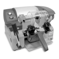
5.4 Description of work station
The key-cutting machine needs only one operator, who has the following controls at his/her disposal:
Control panel:
placed on the left-hand side of the machine; controls the machine completely, through the following
controls:
• master switch (C)
• motor start switch (P)
• push button (M) to activate the brush
• carriage movement lever (L), placed at the bottom left-hand side
• carriage handle (V)
•
carriage release push button
(Q)
Fig. 9
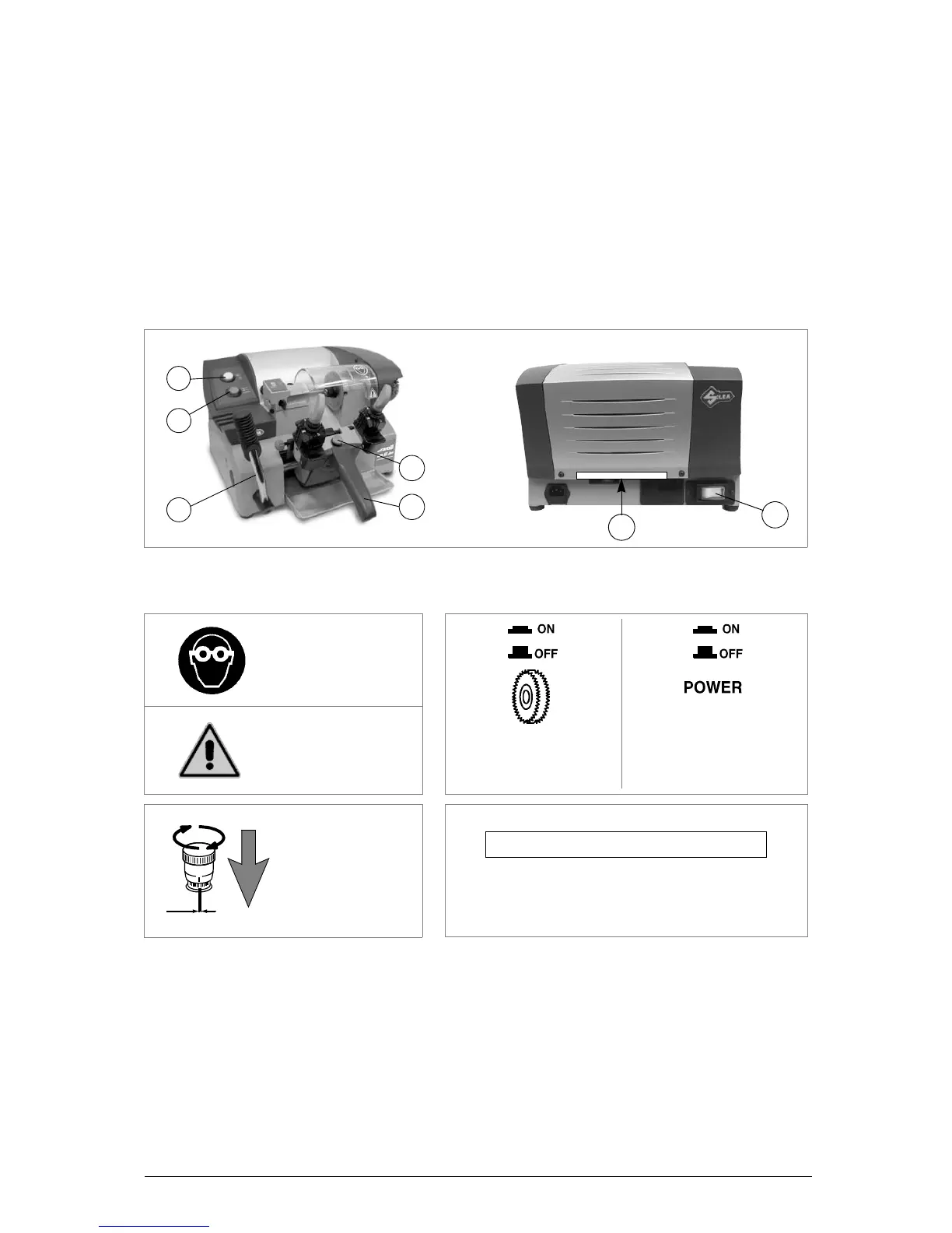
5.5 Graphics
5.6 Separate parts
The separately packed parts must be installed on the BRAVO III with EZ-Jaw key-cutting machine by
the purchaser, as follows:
Connection wire
Connect the supply wire to the inlet on the back of the machine.
5.7 Connection to the mains
For the safety of the operator and the machine it is important to ensure that the machine is connected
to the proper mains voltage by means of an earthed differential switch.
WARNING LABEL (X) (fig.9)
DO NOT EXPOSE TO RAIN OR USE IN DAMP LOCATIONS
NE PAS EXPOSER A LA PLUIE OU DES LIEUX HUMIDES