a. Use the screw size specified in Table 5‑2.
b. Tighten to the torque specified in Table 5‑3.
5. For 1PX and 2PX units, connect the reference phase to A1 X1.3.
6. Connect a current-limited external power source to the auxiliary power input
connector on the bottom of the unit. Connect either:
◦ 90 VAC to 265 VAC (230 V, 150 mA) to connector X1
◦ 24 VDC, 1 A to connector X3
Use the included plug-in, screw-terminal block to make this connection. Follow
the torque recommendation for M2 terminal screws.
7. For HF units, connect the 230 VAC (or 115 VAC special option) fan power
supply to connector X7.
Use the included plug-in, screw-terminal block to make this connection. Follow
the torque recommendation for M2 terminal screws.
8. Reinstall the plastic cover(s) removed for step 1.
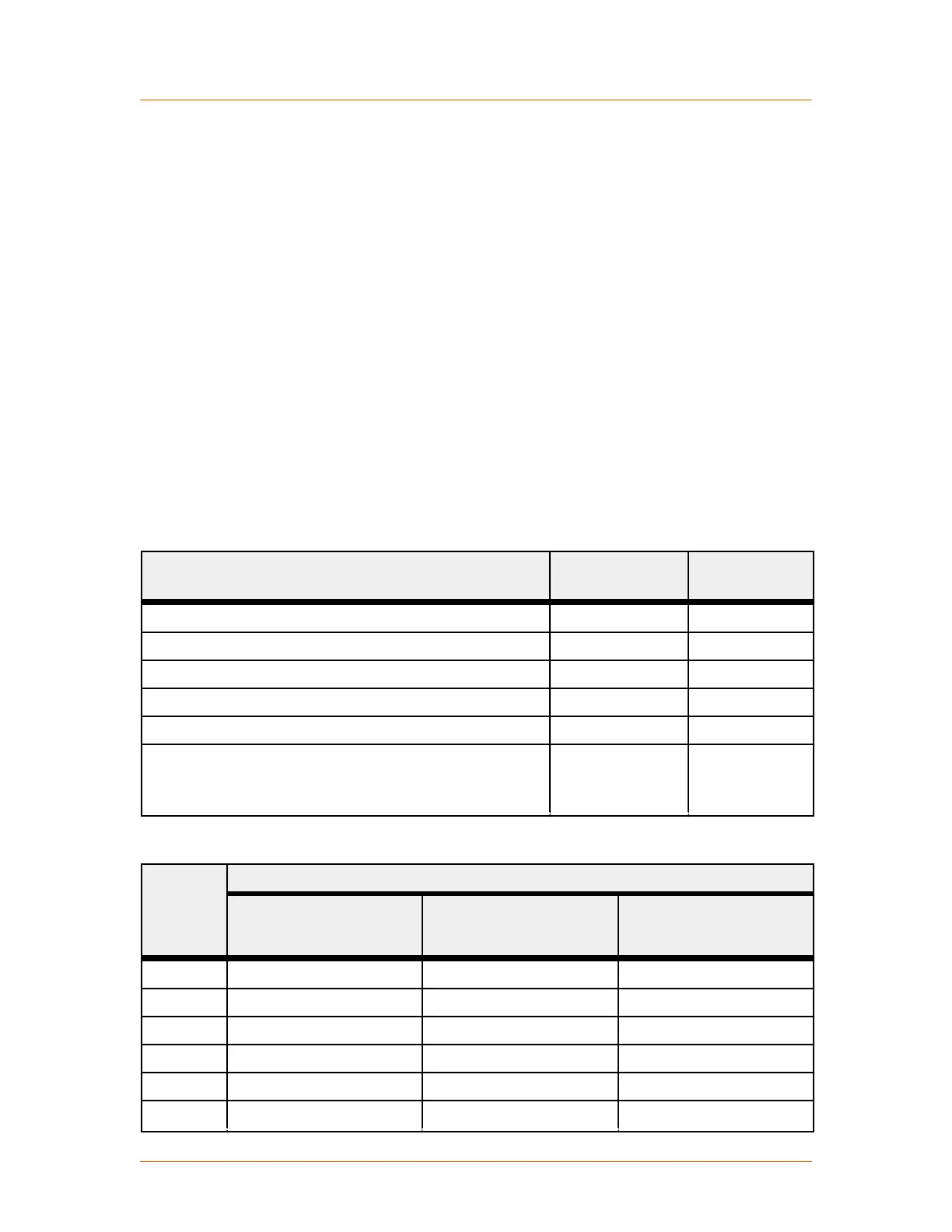
Table 5‑2. Terminal screw size
Model Connector
Screw
Protective
Earth Screw
37 H, 75 H M6 M6
80 H M8 M10
110 H M6 M6
130 H, 170 H M8 M10
200 HF, 280 HF, 300 HF 495 HF, 500 HF, 650 HF M10 M10
780 HF, 1000 HF, 1400 HF, 1500 HF, 1700 HF, 1850 HF,
2000 HF, 2100 HF, 2200 HF, 2400 HF, 2600 HF,
2750 HF, 2900 HF
M12 M12
Table 5‑3. Terminal screw torque
Screw Torque
Minimum NM
(Pound-Inches)
Rated NM
(Pound-Inches)
Maximum NM
(Pound-Inches)
M2 0.2 (1.9) 0.25 (2.2) 0.3 (2.5)
M4 1.0 (8.9) 1.3 (11.5) 1.7 (15.0)
M6 3.0 (26.1) 4.4 (38.9) 5.9 (52.2)
M8 11.5 (101.8) 17.0 (150.5) 22.5 (199.1)
M10 22.0 (194.7) 33.0 (292.1) 44.0 (389.4)
M12 38.0 (336.3) 56.0 (495.6) 75.0 (663.8)
Advanced Energy
®
Thyro-PX
®
Power Controller
57010148-00G Installation, Setup, and Operation 5‑32