#17 Set ‘Buzz’ Amplitude”. In general, increasing this setting
will increase the freeze vibration. However, caution should be
used since too high a value may cause the clapper to become
trapped by the electromagnetic coil.
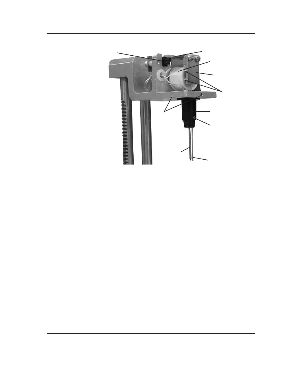
2. Adjust the clapper spacing. Refer to Figure 10. Bend the yoke
(Item 5) to locate the clapper (Item 3) closer to or further away
from the coil (Item 4), whichever is found to increase the
stir/freeze wire tip vibration.
Changing the coil-to-clapper spacing probably will adversely
affect the stir/freeze wire tip location; after bending the yoke,
realign the stir/freeze wire according to the recommendations in
the “Mandrel, Probe, and Stir/Freeze Adjustment” section.
Check the freeze vibration amplitudes as instructed in steps 1 through 5
of this section. Optimum spacing between the coil and clapper should
provide at least 1/2” or 13 mm of tip vibration.
63
Troubleshooting & Service
Figure 10: Operating Head
Mandrel
Setscrews (2)
Sample Probe
Connector (1)
Sample
Probe
Stir/Freeze
Wire
Sample Probe
Setscrew (6)
Stir/Freeze
Wire
Setscrews
Clapper (3)
Yoke (5)
Mandrel
Coil (4)
 Loading...