Replacement Procedure
OsmoTECH® PRO Block Probe
Page 2 222123PM Rev 0
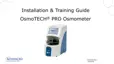
Removing the power supply and controls
assembly
1. Rest the instrument on its back side.
2. Remove the two screws [B] that secure the power
supply and controls assembly to the bottom of the
chassis.
B
3. Place the instrument in the upright position.
4. Remove the two screws [C] that secure the power
supply and controls assembly to the rear of the
chassis.
C
5. Slide the power supply and controls assembly out of
the base assembly.
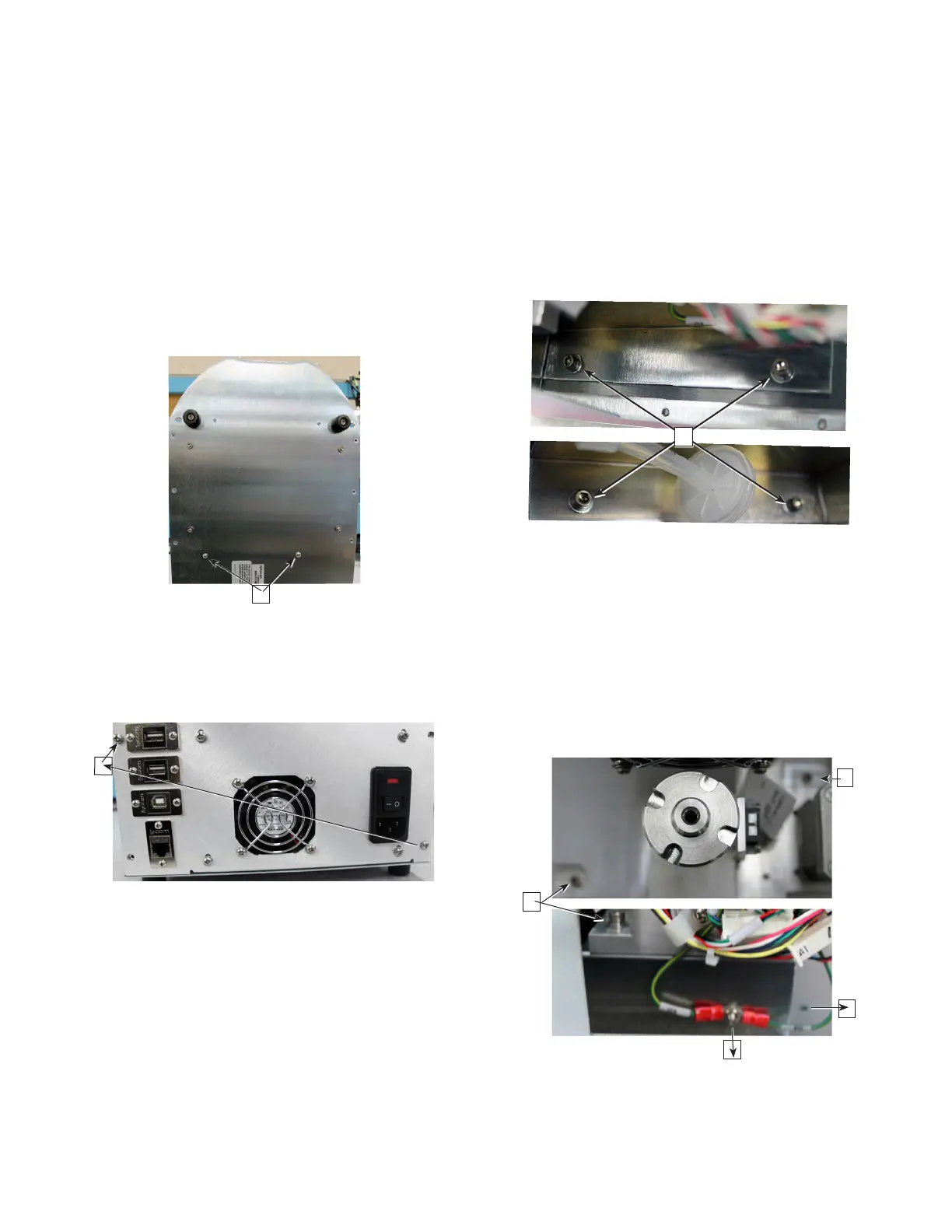
Removing the osmometer module
1. Remove the four socket head cap screws and
washers [D] that secure the osmometer module
mounting bracket to the chassis.
D
2. Carefully slide the osmometer module out of the
instrument.
3. Remove the hex nut and washer [E] that secures the
SPG and BPG ring terminals to the side of the
osmometer module mounting bracket.
4. Remove the four socket head cap screws and
washers [F] that mount the osmometer module to
the osmometer module mounting bracket (which is
secured to the chassis).
F
F
F
E
5. Lift the osmometer module o of the osmometer
module mounting bracket.