6. Repeater Comms Monitoring Type (EN54!)
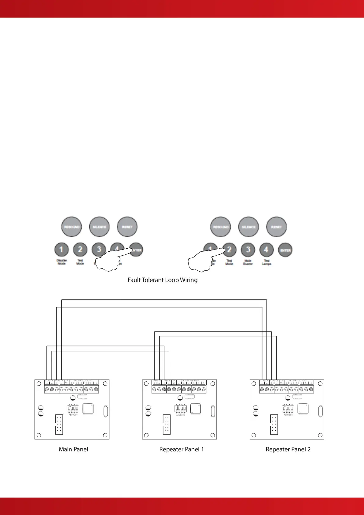
The repeater panels are designed to be wired in a fault tolerant (fail safe) loop configuration, from comms A to B
and back to the main panel again (see drawing below). This enables repeater panels to still work if there is a
break in the cables.
If replacing an older system where the existing cabling cannot be configured in a loop as above, it is possible to
change the panel back to radial circuit comms monitoring.
With the zone 6 fire LED lit, the amber, fault / disabled / test LEDs will show the current setting.
LED 1 OFF = fault tolerant monitoring (default). LED 1 ON = legacy, radial circuit monitoring.
Press the ENTER button, zone 6 fire LED will pulse to indicate ‘edit mode’.
Now use button 2 to change the setting (LED 1 ON or OFF).
When finished press the ENTER button again and the zone 6 fire LED will return to steady ‘view mode’.
Press button 1 to move to next option or press and hold button 1 for 3 seconds to exit programming mode 2-1-2-
3.
When finished all panel wide programming, enter the next programming code or disable the controls and return
DIL switch 6 to ‘OFF’.
www.acornfiresecurity.com
www.acornfiresecurity.com