4. Turn Off Battery Monitoring (EN54!)
The battery monitoring may be disabled for applications where this is appropriate such as non fire alarm use or
where no battery backup is required. Note: No remote PSU fault input is available on the QuickZone XL
With the zone 4 FIRE LED lit, the amber, fault / disabled / test LEDs will show the current setting.
LED 1 OFF = monitored batteries (default). LED 1 ON = batteries un-monitored.
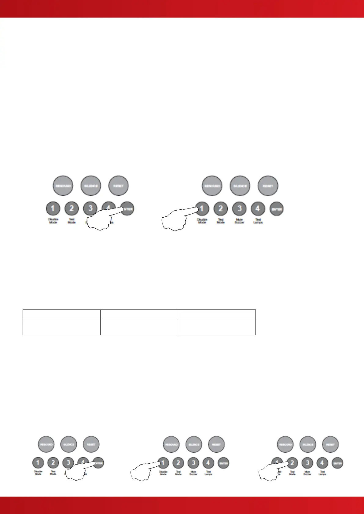
Press the ENTER button, zone 4 fire LED will pulse to indicate ‘edit mode’.
Now use button 1 to change the setting (LED 1 ON or OFF).
When finished press the ENTER button again and the zone 4 fire LED will return to steady ‘view mode’.
Press button 1 to move to next option or press and hold button 1 for 3 seconds to exit programming mode
2-1-2-3.
5. Setup Internal PCB Configuration
The control panel monitors all internal PCBs for correct function. If adding or removing any of the additional
internal PCBs such as extension zone cards or a repeater comms PCB, the panel must be programmed for the
new configuration.
With the zone 5 fire LED lit, the amber, fault / disabled / test LEDs will show the current configuration setting.
Each of the 3 possible additional internal PCBs are represented by LEDs 1 - 3 as per table below.
Extension zone card 1
(zones 5 - 8)
Extension zone card 2
(zones 9 - 12)
Press the ENTER button, zone 1 fire LED will pulse to indicate editing of 1st additional PCB as per table above.
Use button 1 to move to the fire LED for the relevant PCB as per table.
Now use button 2 to change the setting (Amber LED ON = PCB included, OFF = not included).
When finished press the ENTER button again and the zone 5 fire LED will return to steady ‘view mode’, with the
amber, fault / disabled / test LEDs showing the new configuration.
Press button 1 to move to next option or press and hold button 1 for 3 seconds to exit programming mode
2-1-2-3.
www.acornfiresecurity.com
www.acornfiresecurity.com