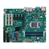
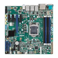
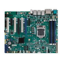
AIMB-275 User Manual 4
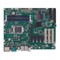
1.4 Jumpers and Connectors
Connectors on the AIMB-275 motherboard link it to devices such as hard disk drives
and a keyboard. In addition, the board has a number of jumpers used to configure
your system for your application.
The tables below list the function of each of the board jumpers and connectors. Later
sections in this chapter give instructions on setting jumpers. Chapter 2 gives instruc-
tions for connecting external devices to your motherboard.
Table 1.1: Connector and Header List
Label Function
SATA1~SATA3 SATA Signal Connector
SATA_PWR1,
SATA_PWR2
SATA Power Connector
MINIPCIE1 MINIPCIE and mSATA Connector
M.2_1 Next Generation Form Factor (M.2 B Key) Connector
M.2_3 NGFF (M.2) screw -80*22mm
M.2_2 NGFF (M.2) screw -42*22mm & 42*30mm
DP1+HDMI1 Display Port and HDMI Common Connector
VGA1 VGA Connector
LVDS1 LVDS Panel Connector
INV1 LVDS Backlight Inverter Power Connector
EDP1 Embedded Display Port Connector
USB56 USB 3.0 Pin Header
USB78, USB910 USB 2.0 Pin Header
LAN1_USB12,
LAN2_USB34
RJ45+USB 3.0 Stack Connector
PCIEX16_1 PCI-E x16 Slot
SPDIF1 HD Digital Audio Interface
AUDIO1, FPAUD1 HD Analog Audio Interface
AMP1 Audio Amplifier Output Connector
GPIO1 General Purpose I/O Pin Header
SPI1 SPI BIOS Flash Socket
SPI_CN1 SPI Programming Pin Header
LPC1 Low Pin Count Header
JSMB1 SMBUS Programming I/F for Vcore Controller
JCASE1 Case-Open Detect Connector
KBMS1 PS/2 Keyboard and Mouse Connector
COM1, COM2 COM Port
CPUFAN1 CPU FAN Power Connector
SYSFAN1, SYSFAN2 SYSTEM FAN Power Connector
ATX12V1 ATX 12V Power Supply Connector
ATX_5VSB1 ATX Power supply (5VSB) connector
BAT1 Battery Holder
CPU1 CPU Socket
DIMMA1, DIMMB1 DDR4 SO-DIMM Socket
 Loading...

