AIMB-275 User Manual 20
2.8.5 Power LED and keyboard lock connector (JFP2/PWR_LED &
KEY LOCK)
(JFP2/PWR_LED & KEY LOCK) is a 5-pin connector for the power on LED and Key
Lock function. Refer to Appendix B for detailed information on the pin assignments.
The Power LED cable should be connected to pin 1-3. The key lock button cable
should be connected to pin 4-5. There are 3 modes for the power supply connection.
The first is “ATX power mode”; the system turns on/off by a momentary power button.
The second is “AT Power Mode”; the system turns on/off via the power supply switch.
The third is another “AT Power Mode” which makes use of the front panel power
switch. The power LED status is indicated in the following table:
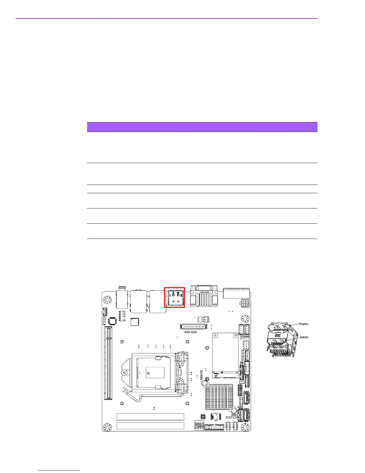
2.9
Display Port and HDMI Common Connector (DP-
HDMI1)
Table 2.2: ATX power supply LED status (No support for AT power)
Power mode
LED
(ATX Power Mode)
(On/off by
momentary button)
LED
(AT power Mode)
(On/off by switching
power supply)
LED
(AT power Mode)
(On/off by front
panel switch)
PSON1
(on back plane)
jumper setting
pins 2-3 closed pins 1-2 closed
Connect pins 1 & 2
to panel switch via
cable
System On On On On
System Off
Off ( Windows 7)
Slow Flashes (Window 8)
Off Off
System Suspend
(S3)
Fast Flashes NA NA
System Suspend
(S4)
Slow Flashes NA NA