AIMB-275 User Manual 14
2.1 Introduction
You can access most of the connectors from the top of the board as it is being
installed in the chassis. If you have a number of cards installed or have a packed
chassis, you may need to partially remove the card to make all the connections.
2.2
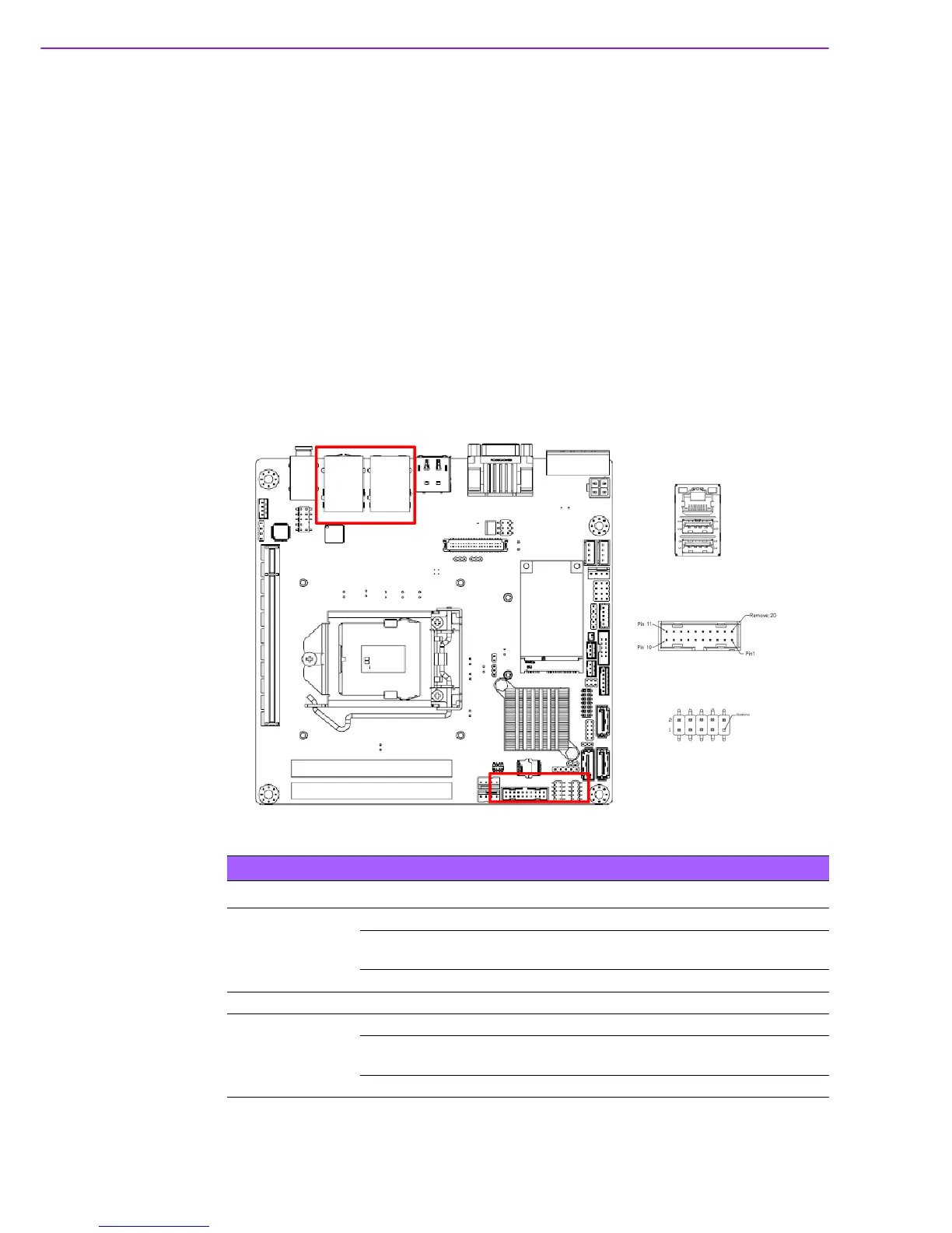
USB Ports (LAN1_USB12/LAN2_USB34/USB56/
USB78/USB910)
The AIMB-275 provides up to ten USB ports. Four USB3.0 on the rear side and six
pin header on the board. The USB interface complies with USB Specification Rev.
2.0 and Rev. 3.0 supporting transmission rates up to 625 Mbps and is fuse protected.
The USB interface can be disabled in the system BIOS setup.
The AIMB-275 is equipped with two high-performance 1000 Mbps Ethernet LAN
adapter, which are supported by all major network operating systems. The RJ-45
jacks on the rear panel provides for convenient LAN connection.
Table 2.1: LAN LED Indicator
LAN Mode LAN Indicator
LAN1 indicator
LED1 (Right) off for mal-link; Link (On) / Active (Flash)
LED2 (Left)
100 Mbps (On) / 10 Mbps (Off);
Color: Orange (10/100 Mbps)
LED2 (Left) 1000 Mbps (On); Color: Green (1000 Mbps)
LAN2 indicator
LED1 (Right) off for mal-link; Link (On) / Active (Flash)
LED2 (Left)
100 Mbps (On) / 10 Mbps (Off);
Color: Orange (10/100 Mbps)
LED2 (Left) 1000 Mbps (On); Color: Green (1000 Mbps)