5 AIMB-275 User Manual
Chapter 1 General Information
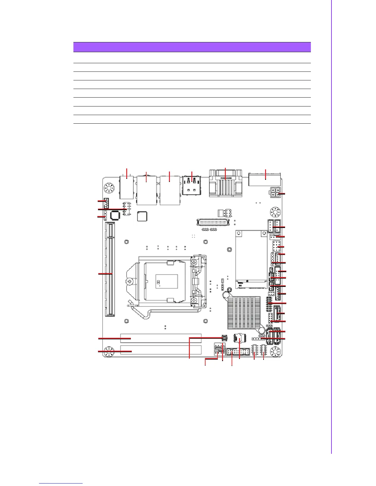
1.5 Board layout: Jumper and Connector Locations
Figure 1.1 Jumper and Connector Location (Top Side)
Table 1.2: Jumper List
Label Function
CMOS1 CMOS Clear Jumper
JFP1 Power Switch/HDD LED/SMBUS/Speaker Pin Header
JFP2 Power LED and Keyboard Lock Pin Header
JWDT1+JOBS1 Watchdog Timer Output and OBS Beep
PSON1 ATX/AT Mode Selection
JLVDS1 LVDS Panel Voltage Selection
JCOM1 COM1 RI# pin RI#/5V/12V Select