- 18 -
www.advateklights.com PixLite 16 Mk2 User Manual V210222
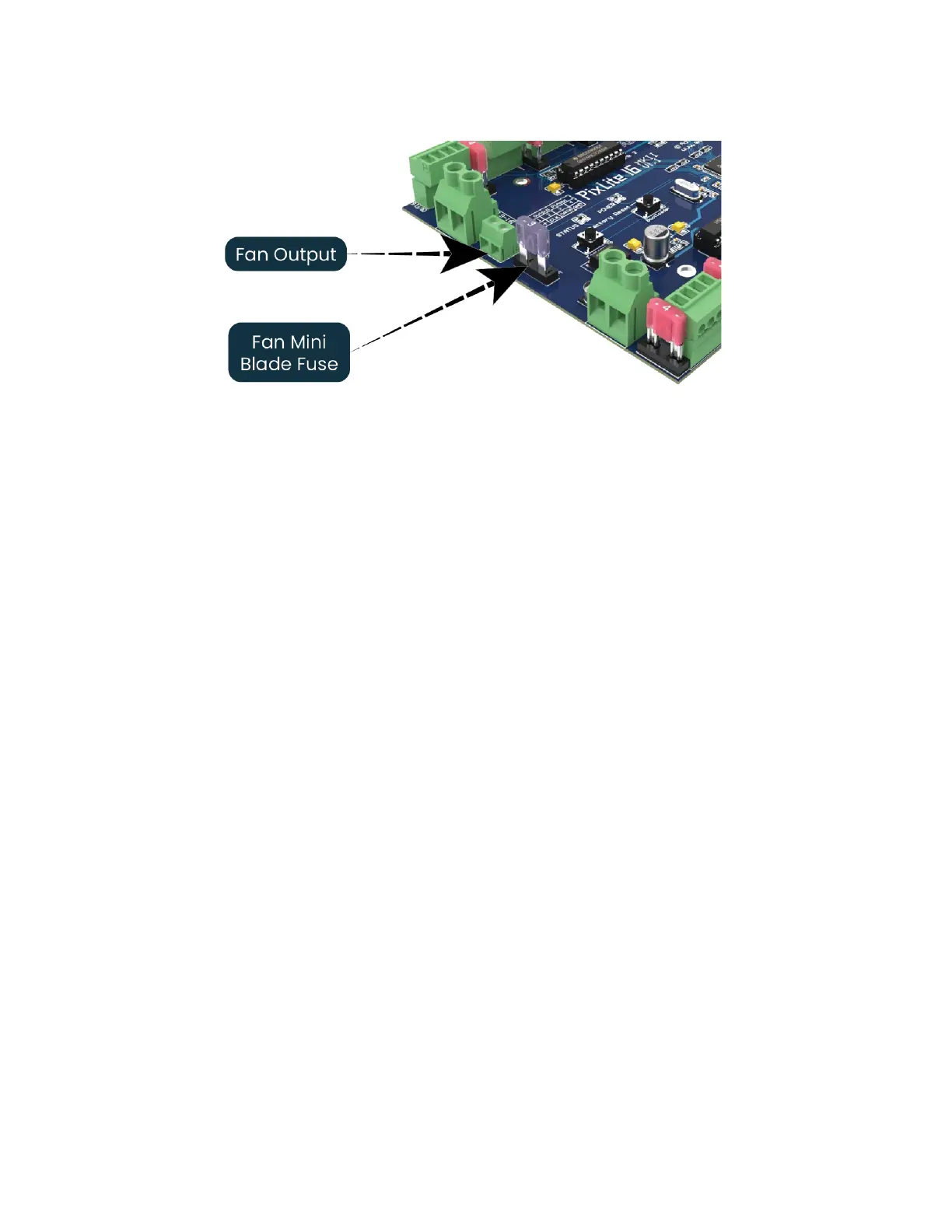
Figure 11: Location of Fan Output
The output voltage of the fan output is the same as the power bank 1 voltage. So, to
run a 12V fan for example, you would need to use a 12V input voltage on bank 1. The
fan output can supply up to 15W of continuous output power and is PWM controlled.
The output is protected by a 3A mini-blade fuse.
Basic operation is as follows: In the Advatek Assistant, the user can set a target
temperature that the enclosure will ideally not exceed. The controller will then
automatically adjust the fan speed based on the current temperature as measured
by the controller’s on-board temperature sensor.
For example, if the target temperature is set at 30°C then sometime before that
temperature, the controller will turn the fan on and slowly ramp up the speed until it
reaches 100% if required, in an attempt to maintain the temperature either at or below
30°C. If the temperature decreases the fan will slow down. The controller will attempt
to keep the temperature below the set point. If the detected temperature reaches the
set temperature, the fan output will be on 100% at this point.
6.4 - Hardware Test Pattern
The controller features a built-in test pattern to assist in troubleshooting during an
installation. To put the controller into this mode, press and hold the ‘Factory IP’ button
for 3 seconds (after the controller is already running) or turn it on remotely from the
“Test” tab in the Advatek Assistant.
The controller will then enter the test pattern mode, where different test patterns are
available as described in the table below. The pattern will display the test pattern on
all pixels on each of the pixel outputs and any enabled DMX512 outputs
 Loading...