1.2.5 “FAULT” indicator: It shows something wrong concerning about the UPS.
1.2.6 “ON” button: With the UPS plugged in, press the “ON” button to turn on the UPS
and power the loads. “ON” also activates the UPS‘s self-test and utility line voltage
displays.
1.2.7 “OFF” button: Press the OFF button to turn off the UPS and the loads.
1.2.8 “SELECT” button (LCD Panel only): The relevant value appears on the upper
screen. There are four display modes can be selected.
Output voltage display
Input voltage display
Input frequency
Temperature inside the UPS
Output frequency.
Load level at percent.
1.2.9 “BATT” bar graph (RECTANGLE INDICATOR): The rectangle indicator shows
the percentage of battery capacity.
1.2.10 “LOAD” bar graph (RECTANGLE INDICATOR): The indicator shows the
power being drawn by the load.
1.2.11 “FAULT” codes (LCD Panel only): The relevant value appears at the upper
screen. There are seven kinds of fault modes can be displayed.
Err0: UPS Fault.
Err1: Warning of overload. (exceeding 120%)
Load Indicator
Light no.5
Light no.4
Light no.3
Light no.2
Light no.1
% of Load Value
over 96%
76-95 %
51-75 %
26-50 %
10-25 %
Battery Indicator
Light no.5
Light no.4
Light no.3
Light no.2
Light no.1
% of Bat Level
over 91 %
76-90 %
51-75 %
26-50%
0-25%
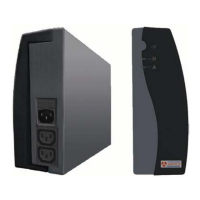
1.3 Rear Panel
1.3.1 TEL./MODEM connector
Telecom transfer ports provide users to extend the applications.
● Caution: To reduce the risk of fire, use only No. 26AWG or larger
telecommunication line cord.
1.3.2 EXTERNAL BATTERY PACK CONNECTOR (optional)
CAUTION: Use only factory supplied or authorized connecting cable for external