INTRODUCTION
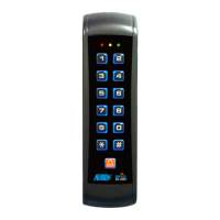
DK-9523 is an universal, self-contained digital access keypad offers field proven reliability and cost effective
solutions for residential and commercial installations. It is designed for stand alone electric lock and inter-lock
systems and operates from a 12 to 24V AC/DC power supply. It is virtually compatible with any electric locking
device. Apart from that it is also the perfect choice for controlling security systems, automatic operators and
machinery.
DK-9523 consists two application softwares of Single User Mode for the general Users, and Multi-User Mode for
the advanced Users. The system offers a 4 digit length user code with 10,000 combinations for each output in
single user mode; and 100 user codes for output 1 and 10 user codes each for output 2 and output 3 in length of
4-8 digits with combinations of more than 100 million in multi-user mode. Operation options of Auto Code entry
and Manual Code entry are available in both two user modes. Programmed information that stored in the system
are non-volatile in power failure.
The DK-9523 offers three outputs with the following facilities:
The connection facilities consist one set of terminal block mainly for Output 1 for door striking purpose; and one
set of wire harness for Output 2 and 3, and the facilities for those auxiliary functions.
5 Amp relay dry contacts, recommended for door strike controls. Normally Open (N.O.) and Normally Closed
(N.C.) outputs are available. Use N.O. output for Fail-secure locking device and N.C. output for Fail-safe locking
device. The relay can be programmed in Start/Stop (toggle) mode or timer mode from 1 to 999 seconds.
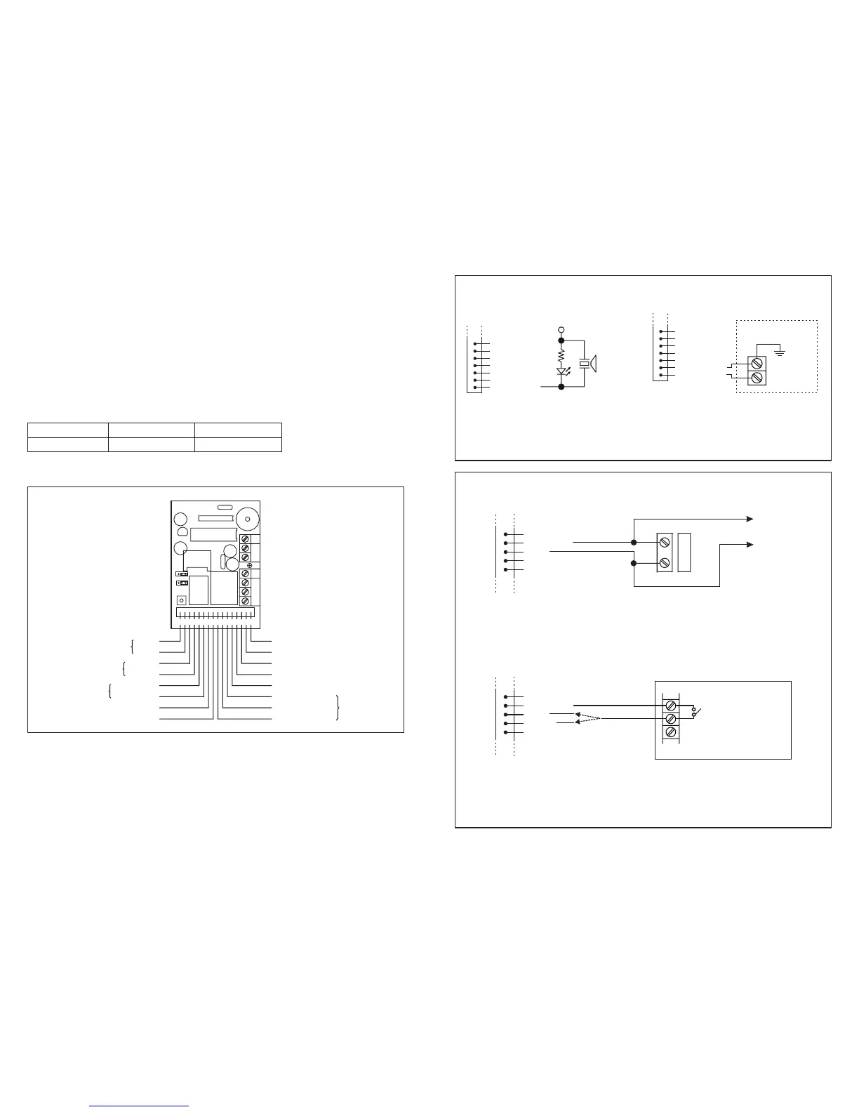
THE TERMINAL BLOCK
!
OUTPUT 1
CONNECTION FACILITIES
2
OUTPUT 1
5 Amp relay
OUTPUT 3
NPN Open Collector
OUTPUT 2
1 Amp relay
WHITE/ORANGE DURESS OUTPUT
YELLOW GREEN ( ) GND-
BROWN INTERLOCK CONTROL
ORANGE OUTPUT 1 INHIBIT
WHITE/RED OUTPUT 3
OUTPUT 2
RELAY
PURPLE (N.C.)
YELLOW (+)
LIGHT BLUE ()-
GREEN (+)
GREY ()-
BLACK
RED
RED LED
GREEN LED
TAMPER
AUXILIARY RED LED ( )- WHITE
KEYPAD ACTIVE OR ALARM OUTPUT PINK
BLUE (N.O.)
WHITE/BROWN (COM)
1
16
2
15
3
14
4
13
5
12
6
11
7
10
89
DK-9523
ON OFF
DAP
KEY AL
KORA
(
+
)( )-
12-24V AC/DC
EG
IN
OUTPUT 1
N.C. C. N.O.
DOOR
SENS
TAMP
RELAY
1
RELAY
2
123 4 567891011 1 213 1415 16
19
The Duress Output will switch to ( ) ground when duress code is entered. You may use it to turn ON an LED
lamp and /or a small buzzer to notify a guard; or connect it to a 24 hour Normally Open protection zone of an
alarm system.
-
F Only one connection option is recommended. Make sure that the sink current does not exceed the maximum
rating of 100mA.
(D) DURESS OUTPUT (WHITE/ORANGE WIRE)
(E) OUTPUT 2
OR
1.5K
LED
+12V
LOW POWER
PIEZO BUZZER
(10)
(11)
(12)
(13)
(14)
(15)
(16) WHITE/ORANGE
WIRE HARNESS
ALARM CONTROL PANEL
24 HOUR N.O.
PROTECTION
ZONE
(10)
(11)
(12)
(13)
(14)
(15) YELLOW GREEN
(16) WHITE/ORANGE
WIRE HARNESS
( i ) Shunting an N.C. Zone (WHITE/BROWN & BLUE WIRES)
F
F
Use the Normally Open (N.O.) output contact to shunt a Normally Closed (N.C.) protection zone of an
alarm system.
Set output contact to Start / Stop Mode (Programming Option 51).
( ii ) Alarm System Arm-Disarm Control (WHITE/BROWN & BLUE or PURPLE WIRES)
F
F
F
Use the (N.O.) or (N.C.) output contact to make arm-disarm control of an alarm system.
Consult your alarm control panel manual for the appropriate output contact to be used in arm-disarm control.
Usually set output 2 to Momentary mode (Programming Option 501) for multi station systems and Start
/ Stop mode (Programming Option 51) for single station systems.
WIRE HARNESS
(8)
(9) WHITE/BROWN
(10) BLUE
(11) PURPLE
(12)
OR
ALARM CONTROL PANEL
REMOTE
ARM-DISARM
CONTROL
NO. OR N.C.
WIRE HARNESS
(8)
(9) WHITE/BROWN
(10) BLUE
(11)
(12)
N.C.
N.C. MAGNETIC CONTACT
TO PROTECTION ZONE
OF AN ALARM CONTROL PANEL