TONES F
FF
---
---
1 Beep
2 Beeps
5 Beeps
Continuous Beeps
1 second Long Beep
LED SIGNALS
ON
1 Flash
2 Flashes
5 Flashes
Continuous Flashes
1 Flash in 2 seconds interval
---
STATUS
1. In programming mode
2. Successful key entry
3. Successful code entry
4. Unsuccessful code entry
5. DAP jumper not replaced
6. In standby mode
7. Output relay activated
!
!
!
!
!
!
!
OUTPUT 2 (9-10-11)
OUTPUT 3 (12)
OUTPUT 1 INHIBIT (13)
INTER-LOCK CONTROL OUTPUT (14)
DURESS OUTPUT (16)
RED & GREEN
AUX RED / GREEN
This is an auxiliary relay output with 1 Amp rating Normally Open (N.O.) and Normally Close (N.C.) dry contacts
controlled by the User Code 2, which is ideal for controlling security systems & automatic operators. It is
programmable for Start / Stop (toggle) operation or timing operation from 1 to 999 seconds.
This is an NPN transistor open collector output ideal for auxiliary control functions, such as controlling security
systems, code Authorization control of output 1 in the keypad etc.
Output 3 is programming for Start / Stop (toggle) operation or timing operation from 1 to 999 seconds. It
switches to ( ) ground in activation and the maximum rating is 100mA sink / 24VDC.
A Normally Open (N.O.) input terminal refers to ( ) ground. Both user code 1 and Egress button can not activate
output 1 while this terminal is tied to ( ) ground. It is prepared for cross wire connection in Inter-lock application.
An NPN transistor open collector output. It is OFF at normal condition and switches to ( ) ground immediately
for the first 5 seconds after keying in a valid user code to operate output 1, then, it will keep tying to ( )
ground during the time that the door position sensor is open due to door opening. Use this output to control the
other keypad (or, the inter-lock controller in power supply, e.g. AD-2312) in an inter-lock system to prevent both
door opening at the same time.
An inter-lock system is a two-door system that always allows only one door to open during the operation time.
While one of the doors in the system is opened, the other door keeps close until the opened door is re-closed
in order to prevent the unauthorized people dashing into a protected area.
An NPN transistor open collector output. It switches to ( ) ground after the Duress Code is entered. Use it to
trigger an alarm zone, or turn on a buzzer to notify a guard. Ic max: 100mA sink. Vc max: 24VDC
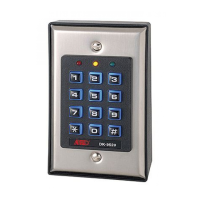
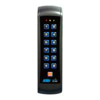
The Red & Green LEDs are prepared for free connection. They give indication
according to installer's connections.
The Green LED at the centre is a status indicator at normal condition. The
lamp changes to steady Red while the auxiliary Red LED is energized.
The built-in buzzer and the green LED indicator at the centre give the following tones and signals for operation status:
All Pacifier Tones can be enabled or disabled through programming options at Location 83.
The Output Activation Beep can be enabled or disabled through programming options at Location 81.
-
-
(AT THE CENTRE)
-
-
-
-
THE LED INDICATORS
THE PACIFIER TONES & THE LED INDICATING
SIGNALS
NOTE: *
**
4
1 2
3
4
5
6
7
8 9
0
#
RED
GREEN
GREEN
& RED
DK-9523
R
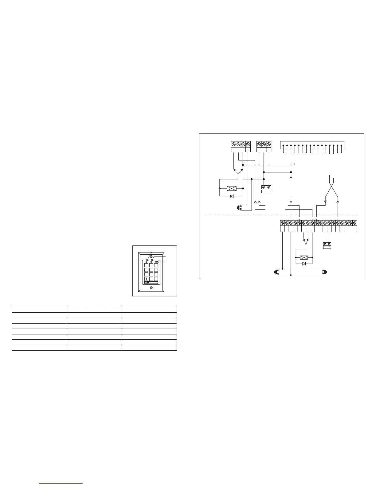
4) BASIC WIRINGS OF AN INTER-LOCK SYSTEM USING KEYPAD AND INTER-
LOCK CONTROLLER POWER SUPPLY
This inter-lock application example utilizes one DK-9523 and a power supply with inter-lock controller, AD-2312. The
power supply provides the power source for the whole system including both electric locks and the keypad. It is
necessary to make sure that the total power consumption of the system does not exceed the maximum power
ratings of the power supply, expecially if fail-safe locks are used. The inter-lock function is accomplished with the
cross wire connection of the "Inter-lock Control Output" and the "Output 1 Inhibit" (or the "EG Stop 1" on AD-2312)
terminals between the keypad and the controller. It is necessary to link up a Common Ground between the keypad
and power supply to set up a power path and to achieve the inter-lock logical functions.
Use keypad to open door 1 from outside.
Open door 2 with egress button A from outside while door 1 is closed.
Open door 1 from inside with egress button; and door 2 with egress button B.
Connect the door magnetic sensors on door 1 and door 2 to monitor their positions.
During the time that door 1 is open, then, door 2 is forced to keep close, or vice versa.
Use N.O. Relay output for fail-secure locking device; and N.C. output for fail-safe locking device.
Relay output 2 of the keypad is independent and has nothing concern with the inter-lock system. It may be used
for other applications, such as controlling security systems.
Please also see the "NOTE" stated in the Application (1) and (2) for the common information.
F
F
F
F
F
F
F
F
17
EG
A
EG
B
EG
C
ALM
STOP
INT.
LOCK
AUTO
LOCK
EG STOP
12
ALARM O/P
N.C. C. N.O.
ELEC. LOCK
() () (+)
SEC SAF 12V
--
(+)
13.7V
()-
GND
()-
GND
DOOR
SENS
LOCK 2
DOOR 2
SENSING
OR
EGRESS BUTTON B
(INSIDE DOOR 2)
EGRESS BUTTON A
(OUTSIDE DOOR 2)
N.O. N.O.
N.C.
AD-2312
EG
IN
OUTPUT 1
N.C. C. N.O.
(
+
)()-
12-24V AC/DC
DOOR
SENS
(+)
(+)
(+)
(+)
(+)
()-
()-
()-
N.O.
EGRESS BUTTON
(OPEN DOOR 1 FROM INSIDE)
TERMINALS CONNECTION HARNESS
123456 7 8910
11 12 13 14 15 16
ELECTRIC
LOCK
N.C. N.O.
OR
1N4004
LED (+)
LED ( )-
DOOR 1
SENSING
N.C.
DOOR 1
DOOR 2
OUTPUT 1 INHIBIT
INTER-LOCK CONTROL
COMMON GND
POWER FOR KEYPAD
POWER FOR LOCK
1 2 4 6 7 10 11 12 13 15 16 17 18
14
9853