APPLICATION HINTS FOR THE AUXILIARY FACILITIES
18
The tamper switch is Normally Closed while the keypad
is secured on gang box. It is open when the keypad is
removed from the gang box. To prevent sabotage,
connect these terminals in series with a 24 hour N.C.
protection zone of an alarm system if required.
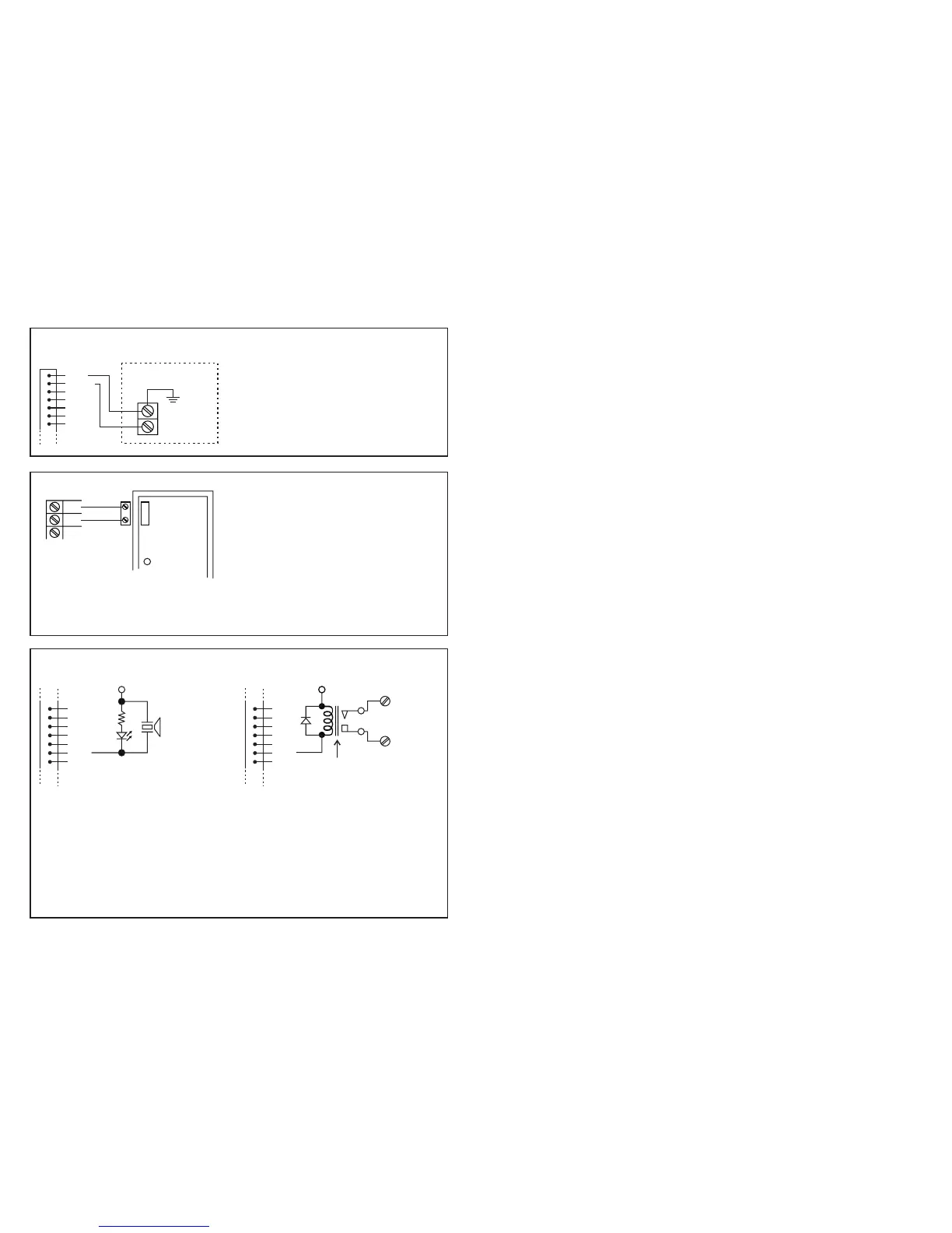
(A) TAMPER N.C. (RED, BLACK WIRES)
ALARM CONTROL PANEL
24 HOUR N.C.
PROTECTION
ZONE
(C) KEY ACTIVE (PINK WIRE)
OR
The Key Active Output will switch to ( ) ground
for 10 seconds whenever a key is touched. You
may use it to turn ON an LED lamp and /or a
small buzzer to notify a guard; or to energize a
relay to switch ON lights or trigger an CCTV
Camera to start recording.
Make sure that the relay for switching ON lights
has high enough isolation between high voltage
and low voltage to prevent damage of the
keypad.
Only one connection option is recommended.
Make sure the sink current does not exceed the
maximum rating of 100mA.
External power supply and isolation relay are
necessary in driving high power device, such as
lights.
-
F
F
F
With the help of a Normally Closed door
position sensor (usually a magnetic door
switch) on the door to set up the following
functions:
a) -- The system will immediately re-
lock the door after a valid access has been gained to
prevent "tailgate" entries.
b) -- The keypad will generate
alarm instantly if the door is forced to open. Enable the
function with Programming Option 801.
c) -- The keypad will generate
alarm if the door is left open longer than the pre-set
delay time. Enable the function with Programming
Option 9 with time of 1 to 999 seconds possible.
d) -- When the door is open, the inter-
lock output of the keypad will give a ( ) command to
stop the other keypad in an inter-lock system.
Door Auto Relock
Door Forced-open Alarm
Door Propped-up Alarm
Inter-lock Control
-
(B) DOOR SENS
DOOR
SENS
()
GND
-
MAGNETIC
DOOR
SWITCH
1.5K
LED
+12V
LOW POWER
PIEZO BUZZER
ISOLATION
RELAY
+12V
N.O.
RELAY CONTACT
(1) RED
(2) BLACK
(3)
(4)
(5)
(6)
(7)
WIRE HARNESS
(3)
(4)
(5)
(6)
(7)
(8) PINK
(9)
WIRE HARNESS
(3)
(4)
(5)
(6)
(7)
(8) PINK
(9)
WIRE HARNESS
!
!
!
!
!
!
EG IN
12 24V AC/DC
DOOR SENS
N.C. TAMPER (1-2)
GREEN, RED & AUXILIARY RED LED LAMPS (3-4), (5-6) & (7)
KEYPAD ACTIVE OUTPUT OR ALARM OUTPUT (8)
EGRESS INPUT
POWER INPUT
DOOR POSITION SENSOR INPUT
NOTE:
Door Auto Re-lock
Door Forced Open Alarm
Door Propped-up Alarm
Inter-lock Control
NOTE:
i) KEYPAD ACTIVE OUTPUT (KEY)
ii) ALARM OUTPUT (AL)
A Normally Open (N.O.) input terminal refers to ( ) ground, with the help of a normally open button to activate the
Output 1 for the same time period as the user code. Egress button is usually put inside the house near the door.
More than one egress buttons can be connected in parallel to the terminal. Leave this terminal open if it is not used.
Connect to 12-24V AC or DC power supply. The ( ) supply and ( ) GND (wire 15) are the common grounding
points of the keypad system. No selection jumper is required for the full input voltage range.
Connect DC power with the (+) and ( ) polarity indicated; and there is no polarity discrimination for AC power input.
A Normally Closed (N.C.) input terminal referring to ( ) ground. With the help of a normally closed magnetic
door switch, the system will monitor the position of the door and will give the following functions:
Always connect this terminal to ( ) ground if not used.
1)
The system will immediately relock the door after valid access has been gained before the end of the
programmed time for output 1, that prevents unwanted "tailgate" entries.
2)
The keypad will generate door forced-open alarm instantly if the door is forced to open without a valid user
entry or egress input. The alarm will last for 60 seconds and can be stopped with user code 1 or one of the
user codes in Group 1 at anytime. This function is selectable via the programming options at Location 80.
3)
When the door is left open longer than the allowable time. The keypad will generate door propped-up alarm
after the expiry of the pre-set door-open-time until the door is closed again. The door-open-time is
programmable from 1 to 999 seconds at Location 9.
4)
The inter-lock control output goes to ( ) while the door is open in order to give signal to disable the other
keypad in the inter-lock system.
Always hold the circuit board tightly and pull the socket out gently to prevent damage of the electronic
assembly of the keypad if the wire harness is required to pull out from the circuit board.
Normally Closed contact while the keypad is secured on the box. It is open while keypad is separated from the
box. Connect this N.C. terminal to the 24 hour zone of an alarm system if necessary.
Three on-board LED lamps are available. They are prepared for free connections. Suggest to connect these LED
lamps to the remote indicator driving terminals of your specific equipment, such as an alarm control panel. Be
sure to observe the polarity (+ & ).
The Green and Red LED lamps that are independent are equipped with 1.5K Ohm current limiting resistor.
The anode of the auxiliary Red LED was connected to +5V internally. It turns ON with the cathode (wire 7)
connecting to ( ) ground.
This is an NPN transistor open collector output with maximum ratings of 100mA sink and 24V DC. It is
selectable to give Keypad Active or Alarm Output via the "K" or "A" Jumper.
--- It switches to ( ) ground for 10 seconds on each key touching. This
can be used to turn on lights, CCTV camera, or buzzer to notify a guard. See Application Hints for more
information.
--- It switches to ( ) ground while Door Forced Open Alarm or Door Propped-up
Alarm occurs in order to trigger external alarm to give notification at remote location.
-
--
-
-
-
-
-
-
-
-
-
THE WIRE HARNESS
3