821 User code Auto Entry Mode (Single-User)
14
APPLICATION EXAMPLES
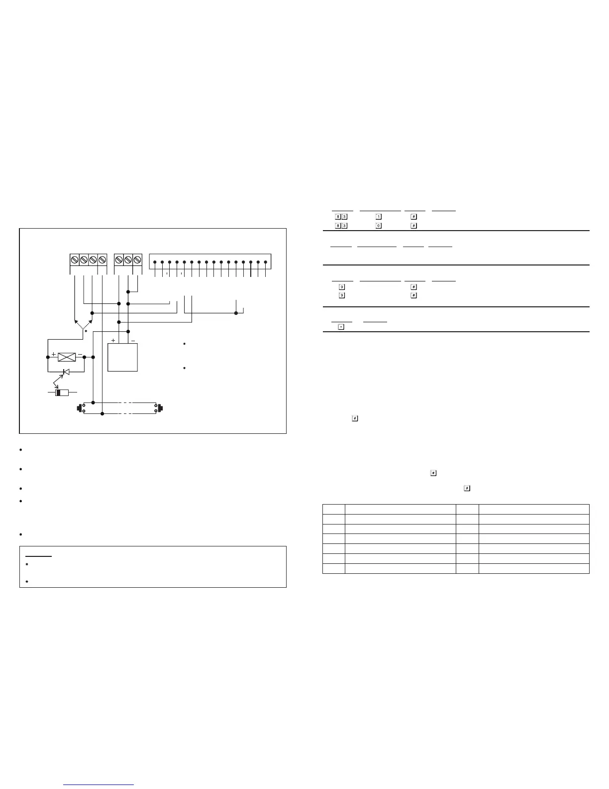
1) BASIC WIRINGS OF A STAND ALONE DOOR LOCK WITH INHIBIT
AUTHORIZATION CODE AND INDICATION
NOTE:
Connect the 1N4004 as close as possible to the lock in parallel with the lock power terminals to absorb the back
EMF to prevent it from damaging the keypad. The 1N4004 is not required if the electric lock is AC operated.
To avoid Electro-Static-Discharge from interfering with the operation of the keypad, always ground the ( ) GND
terminal of the keypad to earth.
The Green LED lights up during the keypad is striking the electric lock.
Connection of "Output 3" to "Output 1 Inhibit" is optional. With this connection, output 3 is used as authorization
control. The owner may key in the User Code 3 to stop the operation of the electric lock in the night time or
after office hour to prevent unauthorized access. Set output 3 in Start / Stop mode (Programming Option 61) for
ON-OFF control. The Red LED lights up while the operation of the electric lock is stopped.
Tape all the un-used wires to prevent short circuit.
-
WARNING
FOR SAFETY, MAKE SURE NOBODY INSIDE THE HOUSE BEFORE YOU START THE DOOR LOCK INHIBIT
FUNCTION. THE LOCK LOCKS ALL THE TIME DURING "INHIBIT" IS ON DUTY.
THE INHIBIT AUTHORIZATION CODE SHOULD ALWAYS BE KEPT BY THE OWNER BUT NOT OTHER USER(S).
EG
IN
OUTPUT 1
N.C. C. N.O.
(
+
) ( )-
12-24V AC/DC
DOOR
SENS
(+)
(+)
(+)
( )
( )
N.O. N.O.
EGRESS BUTTON
(INSIDE THE HOUSE)
MORE EGRESS BUTTONS
CAN BE CONNECTED IN PARALLEL
REMARKS:
OUTPUT RELAY 1
N.O. Output for Fail-secure Lock
N.C. Output for Fail-safe Lock
LEDS
Each LED Requires a 1.5K Ohm Series
Resistor on 24V Operation
TERMINALS CONNECTION HARNESS
1 2 3 4 5 6 7 8 9
10
11 12 13 14 15 16
ELECTRIC
LOCK
N.C. N.O.
OR
12V DC
POWER
SUPPLY
CATHODE
1N4004
GREEN LED
GREEN LED
RED LED
RED LED
O/P 1 INHIBIT
OUTPUT 3
I) Pacifier Tones (Keypress Acknowledgement Tones)
K) Allowable Time to Start Door Propped-up Alarm
Single User Mode (Command Code: 8900)
--
--
Installer Programming
Installer Programming
Single User Mode is prepared for the simple users, which allows only one user code to operate each output. The
user codes are fixed to 4 digits and 10,000 code combinations are possible. User codes can be programmed directly
into the User Code Locations 1, 2 and 3 respectively for the three outputs. Please see Programming Summary Chart
Section (C), item i) for details. This mode is always set with Auto Code Entry in default. The user does not require
to press the key in user code entry. The user only needs to enter the 4 digit user code. The relay will activate for
the programmed time.
The system can be set for Manual Entry with programming option 0 at Location 82 if required.
Multi-User Mode allows up to 100 individual user codes to operate the output 1 and 10 each individual user codes
to operate the output 2 and 3. The user codes can be 4 to 8 digits with over 100 million code combinations. The
user codes can be set for Auto Entry or Manual Entry with programmin
g options at
Location 82. Manual Entry
Mode is in default. The user code followed by key is required.
Once the keypad is programmed in Auto Entry, the Master Code and the User Codes MUST be set in the same digit
length, and the need for the user code not to be followed by key is required.
Pacifier tones available on keypress
All pacifier tones are off. Good for place requires silent environment
0 No propped-up alarm
1 to 999 Allowable time from 1 to 999 seconds for door left open before the door
propped-up alarm starts
L) Exit Programming Mode
Keypad exits programming mode and returns to normal operation
SINGLE USER MODE OR MULTI-USER MODE SELECTION
The keypad consists two sets of software for owner's selection in user code programming. They are "Single User
Mode" and "Multi-User Mode".
The keypad has been set with a Master Code of "0000" and in Single User Mode at the factory. If your required
mode is Multi-User, you have to refresh the system with the appropriate comment code, 8901, to set it into Multi-
User Mode.
NOTE:
Locations Code of Functions Validation Comments
Locations Code of Functions Validation Comments
All the default values in Multi-User Mode and Single User Mode are exactly the same except the User
Code Entry Mode.
Validation Comments
Multi-User Mode (Command Code: 8901)
The Default Values
NOTE: **
7
Default Comments Default Comments
**
**
401 Output 1 in 1 second Momentary Mode
501 Output 2 in 1 second Momentary Mode
601 Output 3 in 1 second Momentary Mode
70
800 Door forced-open alarm disabled
811 Output relay activation beep ON
820 User code Manual Entry Mode (Multi-User)
831 Pacifier Tones ON
841
Main LED flashing in normal mode during
system standby
90 No propped-up alarm
After 10 successive false code, the keypad
locks during 30 seconds
J) Main LED Flashing ON-OFF -- Installer Programming
Locations
Validation
Code of Functions
Comments
Main LED flashing in normal mode during system standby
Main LED OFF during system standby