11
7/12/2017 - DOCUMENT NUMBER: 10-0300
© 2017 AEM Performance Electronics
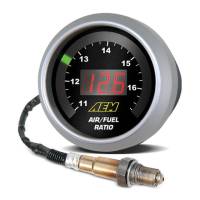
30-0300 X-Series UEGO Gauge
parallel to AEMnet+/AEMnet- (or CANH/CANL) at both
physical ends of the bus run. The X-Series controller does
not have any internal termination and is intended to be
connected to a pre-existing, properly terminated network.
Please refer to the Bosch CAN2.0B specification for further
detail.
Serial (RS-232) Output
BLUE WIRE = Serial Out
The serial datastream is suitable for output to third party devices such as data
loggers, PCs, or reflashed ECUs. The X-Series UEGO serial datastream is
designed to match AEM's legacy 30-4100/30-4110 UEGO Digital Gauge for
backwards compatibility. The currently selected display mode (lambda or AFR)
will dictate what is output via serial. The format is simply the value followed by a
carriage return and line feed, e.g. "14.7\r\n"
FAQ / Troubleshooting
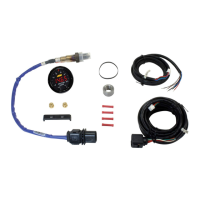
What are the minimum wiring connections needed to use the gauge?
Switched/fused 12V (RED) and power ground (BLACK) must be supplied to the 10 pin connector. Any unused wires may
be secured and fastened away for future use. The 8 pin sensor harness must also be connected between the gauge and
sensor.
When should I use free air calibration mode?
The sensor that is supplied is laboratory calibrated using the integral trim resistor; this is the preferred and recommended
calibration mode. If you feel your sensor has been extremely contaminated or damaged and requires re-calibration then it
is suggested that you purchase a new sensor. Alternatively, performing a free air calibration may be helpful.
The gauge displays "bAtt" when I key-on or crank the engine.
 Loading...